


CONCEPTSYSTEM EXAMPLESCONNECTIONSPRODUCTSBLOCK DIAGRAMS
63
4
PRODUCTS
WU-ZS001E
CONCEPT SYSTEM EXAMPLES CONNECTIONS PRODUCTS BLOCK DIAGRAMS
62
4
PRODUCTS
WU-ZS001E
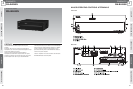
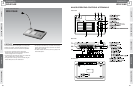
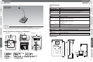
Surveillance Unit
WU-ZS001E
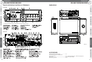
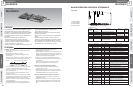
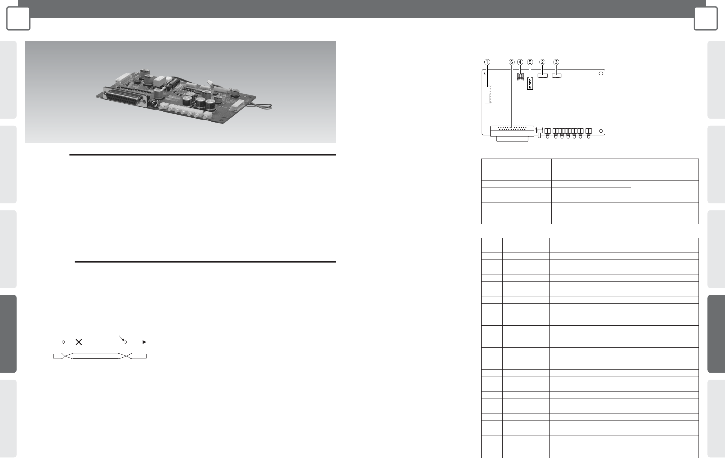
MAJOR OPERATING CONTROLS & TERMINALS
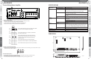
Top of Unit
1 CN101 Terminal
2 CN102 Terminal
3 CN103 Terminal
4 CN104 Terminal
5 DIP Switches
6 SURVEILLANCE I/F Connector
PREFACE
This Surveillance Unit is intended for installation on the WA-
MA120N/240N Mixing Power Amplifier (sold separately).
Installation of the Surveillance Unit ensures system reliability
and safety by detection of speaker line failures, as well as
audio signal problems and abnormally high temperatures in
the amplifier.
• Detects and notifies speaker line faults (shorts,
disconnections, grounding), amplifier audio signal
problems, and abnormally high amplifier temperatures.
• A built-in interval timer schedules automatic checks for
speaker line failures at a preset interval.
• Non-stop monitoring for amplifier audio signal problems and
abnormally high temperatures, and notifies when
abnormalities are discovered.
• Speaker line failure detection can be executed by Sound
Message Unit scheduler.
• Switch operation allows manual execution of speaker line
check.
• SURVEILLANCE I/F connector supports execution of
speaker line check and acquisition of each fault notification.
• Fault notification from the SURVEILLANCE I/F connector
allows configuration of a system that switches to a backup
amplifier when the power amplifier has a problem.
FEATURES
•
Speaker Line Check
• Speaker lines can be checked individually for shorts and
disconnections.
• Overall speaker line check for grounding.
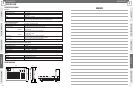
• Speaker line check is performed according to the time
interval setting.
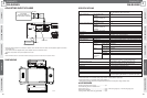
Notification about any faults occurred during the time interval
will not be made at once. See the illustration below for
details.
• Check interval can be set to none, 10 minutes, 60 minutes,
or 24 hours. The factory default setting is 24 hours.
• Execution of speaker line failure detection cancelled during
all-zone announcement.
And it will not be resumed automatically when all-zone
announcement ends.
• Indicators on the front panel of the mixing power amplifier
signal malfunction. Notification of the fault is also sent from
the SURVEILLANCE I/F connector at the same time.
Detection of a short in a speaker line causes automatic cut
off of the line's output.
• CHECK/SETTING switch can be used to execute the
speaker line check or to set the line impedance reference
value. The same setting is also possible from the
SURVEILLANCE I/F connector.
• The Surveillance Unit's indicator and the FAULT indicator on
the front of the mixing power amplifier flash to indicate that
speaker line failure detection is in progress and while the line
impedance reference value is being obtained.
• Detection of a short causes the applicable line to be cut.
• The speaker line check will not be performed during all-zone
announcement.
And when there is no all-zone announcement, it will be
performed as scheduled by the time interval setting.
•
Detection of Amplifier Audio Signal Problems
• Audio output of the amplifier is constantly monitored to
ensure operation is normal.
• Indicators on the front panel of the mixing power amplifier
signal problems. Notification of the problem is also sent from
the SURVEILLANCE I/F connector at the same time.
•
Detection of Abnormally High Amplifier Temperature
• The amplifier is constantly monitored to ensure normal
temperature increase.
• Indicators on the front panel of the mixing power amplifier
signal abnormalities. Notification of the abnormality is also
sent from the SURVEILLANCE I/F connector at the same
time.
Check
Fault
Next fault detection and notification
Check
(n-1)
(n)
Time
Time interval
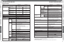
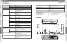
DIP Switch
Name Description Settings Factory
Number Default
1 Fixed settings Fixed at factory default setting – ON
2 TIMER1 Interval timer setting 1 None/10 minutes/
24 hours
3 TIMER2 Interval timer setting 2
60minutes/24 hours
4 MASTER/SLAVE Master/slave setting MASTER/SLAVE
MASTER
5
POWER ON CHECK
Power on speaker line check setting
ON/OFF ON
6
BUS SYNC ENABLE
Speaker line test sync on/off for ON/OFF OFF
multi-amp connection
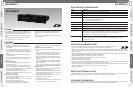
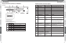
Pin Number
Signal Name
IN/OUT Signal/Logic
Required Action
1 ZONE1 SHORT OUT Active Low Zone 1 speaker line is shorted.
2 ZONE1 OPEN OUT Active Low Zone 1 speaker line is disconnected.
3 ZONE2 SHORT OUT Active Low Zone 2 speaker line is shorted.
4 ZONE2 OPEN OUT Active Low Zone 2 speaker line is disconnected.
5 ZONE3 SHORT OUT Active Low Zone 3 speaker line is shorted.
6 ZONE3 OPEN OUT Active Low Zone 3 speaker line is disconnected.
7 Reserved
8 Reserved
9 Reserved
10 Reserved
11 GROUND FAULT OUT Active Low Some speaker lines are grounded.
12
PA SIGNAL FAULT
OUT Active Low Power amplifier audio signal is faulty.
13
CHECKING/SETTING
OUT Active Low
During measurement of the speaker line reference
BUSY
impedance or during check of the speaker lines.
14
REFERENCE ERROR
OUT Active Low
The speaker line reference impedance couldn’t
be measured successfully.
15 GND GND GND
16 PA TEMP FAULT OUT Active Low Power amplifier temperature is faulty.
17 COMM FAULT OUT Active Low Serial Communication is faulty.
18 Reserved
19 Reserved
20 Reserved
21 GND GND
22
CLOCK ADJ CONT
IN
One-shot make
Adjust control of Interval clock
23
SP LINE REFERENCE
IN
One-shot make
Measurement of the speaker line reference
SETTING ACTIVATION
impedance (Initial setting) starts.
24 SP LINE CHECK IN
One-shot make
Check of the speaker line impedance starts.
ACTIVATION
25 GND GND GND