


CONCEPTSYSTEM EXAMPLESCONNECTIONSPRODUCTSBLOCK DIAGRAMS
17
3
CONNECTIONS
WA-MA120N/WA-MA240N
CONCEPT SYSTEM EXAMPLES CONNECTIONS PRODUCTS BLOCK DIAGRAMS
16
3
CONNECTIONS
WA-MA120N/WA-MA240N
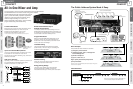
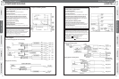
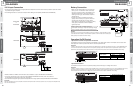
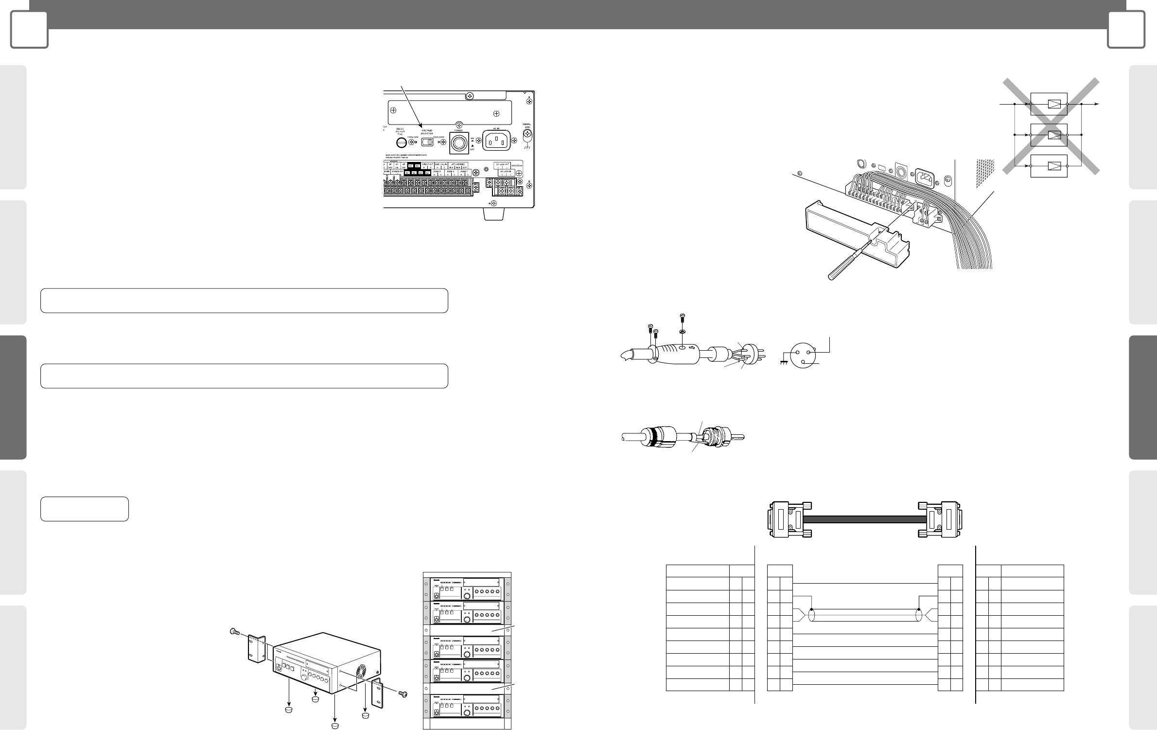
INSTALLATION
AC Voltage Setting
• Before plugging the AC power plug into the mains, make sure the VOLTAGE
SELECTOR switch on the back of the Amplifier is in the proper position.
• The factory preset is 220 V to 240 V. The Amplifier will not operate correctly if the
VOLTAGE SELECTOR is set to 220 V to 240 V while the AC voltage is 110 V to 120 V.
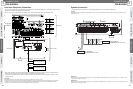
CONNECTIONS
Important:
• The Amplifier's output power cannot be increased if multiple Amplifiers (or WA-BA240N Booster Power
Amplifier) are inputting and outputting the same signal "in parallel operation" because it will short
circuit. Absolutely do not connect the Amplifiers together in parallel operation, doing so may result in a
malfunction.
Backup for AC Power Cut
• Do not use UPS (Uninterruptible Power Supply) as backup in case of AC power cut.
Use external batteries instead.
Replacing the Fuse
• If the fuse blow, replace it with a fuse that is the same shape and capacity. The wrong type of fuse
will be prone to blowing even under normal conditions, and creates the risk of danger if the
Amplifier malfunctions.
Rack Mounting
Precautions
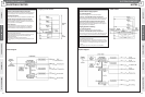
External Battery Precautions
Note the following precautions when using an external battery.
• Make sure the external battery is a 24 V Lead Acid battery (or two 12 V batteries in series connection). Panasonic Corporation holds
no responsibility for any Amplifier fault operation or other inconveniences resulting from using any other batteries except that indicated
above.
•
Use the formula below to determine the battery capacity that is necessary to support the amount of operating time required. Note, however,
that the actual amount of operation time provided by a battery varies greatly in accordance with the Amplifier's signal output Level.
•
When connected to an external battery, the Amplifier will automatically switch to the battery power supply once the AC power supply is
cut off by turning off the POWER switch or due to power cut. The battery power is not cut off even when the POWER switch on the
back of the Amplifier is turned off. The battery power consumption continues even when both the OPERATE and the POWER switches
are off and the OPERATE indicator remains lit amber. Use the formula below to determine the battery life.
To save the power of the battery, switch off both the POWER and the OPERATE, remove the battery if the Amplifier is not in use for a long period.
•
No battery power will be consumed only if the AC power is connected. And the Amplifier has no built-in battery charger. Note that the battery
discharges even when it is not in use, so observe the battery's instructions and check the battery periodically. Be sure to remove the battery
from the Amplifier before charging. And charge the battery properly according to the instructions of the battery and the battery charger.
•
The Amplifier operates normally with the battery voltage over 21 V, and audio output malfunction may occur if the voltage is lower than 21 V.
Battery Capacity [AH] = Amplifier Normal DC Consumption Current [A]* x Required Operating Time [H]
* Based on IEC60065 standards. Refer to the SPECIFICATIONS (page 48).
Battery Life [H] = Battery Capacity [AH] ÷ Amplifier Standby DC Consumption Current [A]*
* Please refer to the SPECIFICATIONS (page 48).
WA-MA120N: 15 A
WA-MA240N: 30 A
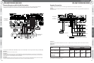
Cautions:
• Refer all work related to the installation and maintenance of the external battery to qualified service personnel or system installers.
• Be sure to turn off power (AC) before installing or removing a battery. To protect the battery, provide one of the fuses shown below between
the battery + terminal and the Amplifier's + terminal.
Take care to ensure proper battery polarity and to avoid shorts while working.
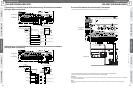
Installing Rack Mounting Brackets
• Installing the supplied rack mounting brackets lets you
configure the Amplifier for rack mounting.
1. Remove the screws (M5 x 16) from both
sides of the Amplifier.
2. Use the four screws (M5 x 16) to attach
the rack mounting brackets.
• Also remove the four rubber feet on the bottom of the
Amplifier by using a flat blade screwdriver to pry out the
pins that hold the feet in place.
VOLTAGE SELECTOR
switch
Blank
Panel
Blank
Panel
PA
Amplifier
PA
PA
OUTIN
G (Ground)
H (Hot)
C (Cold)
3
2
1
Screw
Spring washer
3 (Cold)
2 (Hot)
1 (Ground)
Hot
Ground
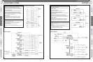
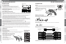
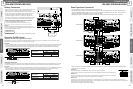
Cables and Connectors
Cable with XLR-3-12 Type (Male) Connector
Use this type of cable to connect to inputs 1 through 3. Use a connector that is wired pin 2 hot.
Cable with RCA Pin Plug
Use this type of cable to connect to LINE 1, LINE 2, REC OUT, LINE OUT, INPUT D-OUT, and INS IN/THRU/OUT.
Cable with D-sub 9 pin (Male) Connector on both Ends (inch-pitch screw)
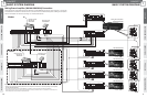
Use this type of cable to link the ALL CALL BUS connectors when connecting multiple Amplifier units together.
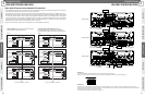
Removing the Terminal Cover
1. Loosen the screw that secures the
terminal cover.
2. Remove the terminal cover.
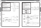
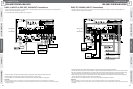
ALL CALL BUS COLD
ALL CALL BUS HOT
GND
GND
GND
Control Terminal
Control Terminal
Control Terminal
Control Terminal
ALL CALL BUS COLD
ALL CALL BUS HOT
GND
GND
GND
Control Terminal
Control Terminal
Control Terminal
Control Terminal
Pin No. Pin No. Pin No. Pin No.
Signal Name Signal Name
Amplifier A
ALL CALL BUS THRU
Amplifier B
ALL CALL BUS IN
Shielded Cable
D-sub 9 pin (Male) connector
(inch-pitch screw)
D-sub 9 pin (Male) connector
(inch-pitch screw)
1
2
6
7
8
9
3
4
5
1
2
6
7
8
9
6
7
8
9
3
4
5
1
2
3
4
5
6
7
8
9
1
2
3
4
5
• Use a straight cable with all pins wired. Be sure to use shielded cable only for audio signal connections.
• General RS422 cable can be used for short distances of a few metres.