


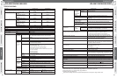

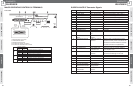
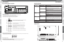
Pin Number
Signal Name Meaning Required Action
1 ZONE1 SHORT Zone 1 short Check for short in wiring of Zone 1.
2 ZONE1 OPEN Zone 1 disconnection Check for disconnection in wiring of Zone 1.
3 ZONE2 SHORT Zone 2 short Check for short in wiring of Zone 2.
4 ZONE2 OPEN Zone 2 disconnection Check for disconnection in wiring of Zone 2.
5 ZONE3 SHORT Zone 3 short Check for short in wiring of Zone 3.
6 ZONE3 OPEN Zone 3 disconnection Check for disconnection in wiring of Zone 3.
7 Reserved
8 Reserved
9 Reserved
10 Reserved
11 GROUND FAULT Zone grounding Grounding
12 PA SIGNAL FAULT Power amplifier audio Check the amplifier’s power amplifier circuit.
fault
13 CHECKING/SETTING Speaker line check in
BUSY progress
14 REFERENCE ERROR Speaker line reference There is a short or ground fault in one of the
value error speaker lines. Identify the line in accordance with
the indicators or SURVEIL LANCE I/F, and check
for location of the short in the applicable line.
15 GND GND GND
16 PA TEMP FAULT Power amplifier high Check for a faulty fan, and check amplifier’s
temperature fault power amplifier circuit.
17 COMM FAULT Communication error Check the amplifier’s internal wiring. Also
notification check the Sound Message Unit for faults.
18 Reserved
19 Reserved
20 Reserved
21 GND GND GND
22 CLOCK ADJ CONT Clock adjustment input
23 SP LINE REFERENCE SP line reference
SETTING ACTIVATION setting activation
24 SP LINE CHECK SP line check
ACTIVATION activation
25 GND GND GND
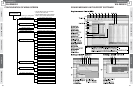
CONCEPTSYSTEM EXAMPLESCONNECTIONSPRODUCTSBLOCK DIAGRAMS
65
4
PRODUCTS
WU-ZS001E
CONCEPT SYSTEM EXAMPLES CONNECTIONS PRODUCTS BLOCK DIAGRAMS
64
4
PRODUCTS
WU-ZS001E
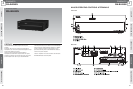
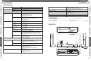
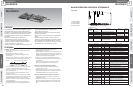
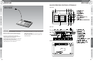
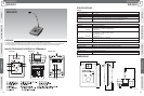
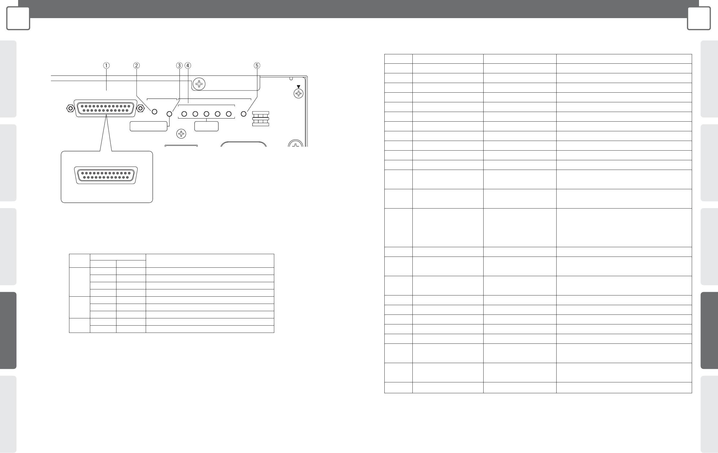
MAJOR OPERATING CONTROLS & TERMINALS SURVEILLANCE I/F Connector Signals
Front of Unit
/DC OUT
T1AL
VOLTAGE
GND
SELECTOR
AC IN
SIGNAL
POWER
RM DC
STATUS/SETTING
CHECK SETTING
SP LINESURVEILLANCE I/F
5
ZONE
4321
GROUND
FAULT
SP LINE FAULT
RED-SHORT
AMBER-OPEN
AMBER-NO SETTING
GREEN-SETTING COMPLETED
13 1
25 14
1 SURVEILLANCE I/F Connector
2 CHECK/SETTING Switch
3 SETTING STATUS Indicator
4 SP LINE FAULT ZONE 1-5 Indicators
5 SP LINE FAULT GROUND FAULT Indicator
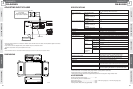
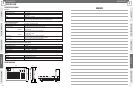
Code
Indicator Condition
Meaning
Colour Status
Amber Lit Reference value not set or abnormal
3
Amber Flashing Reference value setting operation in progress
Green Lit Speaker line check enabled (reference value set correctly)
Green Flashing Speaker line check in progress
Red Lit Speaker line is shorted (SHORT)
4 Amber Lit Speaker line is disconnected (OPEN)
– Unlit No speaker line short or disconnection
5
Red Lit Speaker line is grounded fault
– Unlit No speaker line grounding fault