2726
CONCEPTSYSTEM EXAMPLESCONNECTIONSPRODUCTSBLOCK DIAGRAMS
3
CONNECTIONS
WA-MA120N/WA-MA240N
CONCEPT SYSTEM EXAMPLES CONNECTIONS PRODUCTS BLOCK DIAGRAMS
3
CONNECTIONS
WA-MA120N/WA-MA240N
Important 2
Important 1
Important 1
Important 2
Important 2
Amplifier (Area 1)
Amplifier (Area 2)
Amplifier (Area 3)
Amplifier (to Area 4)
Connect to
each input device
Connect to
each input device
Connect to
each input device
To Area 1, Zone 1 to 3 speakers
To Area 2, Zone 1 to 3 speakers
To Area 3, Zone 1 to 3 speakers
Important 1
Important 1:
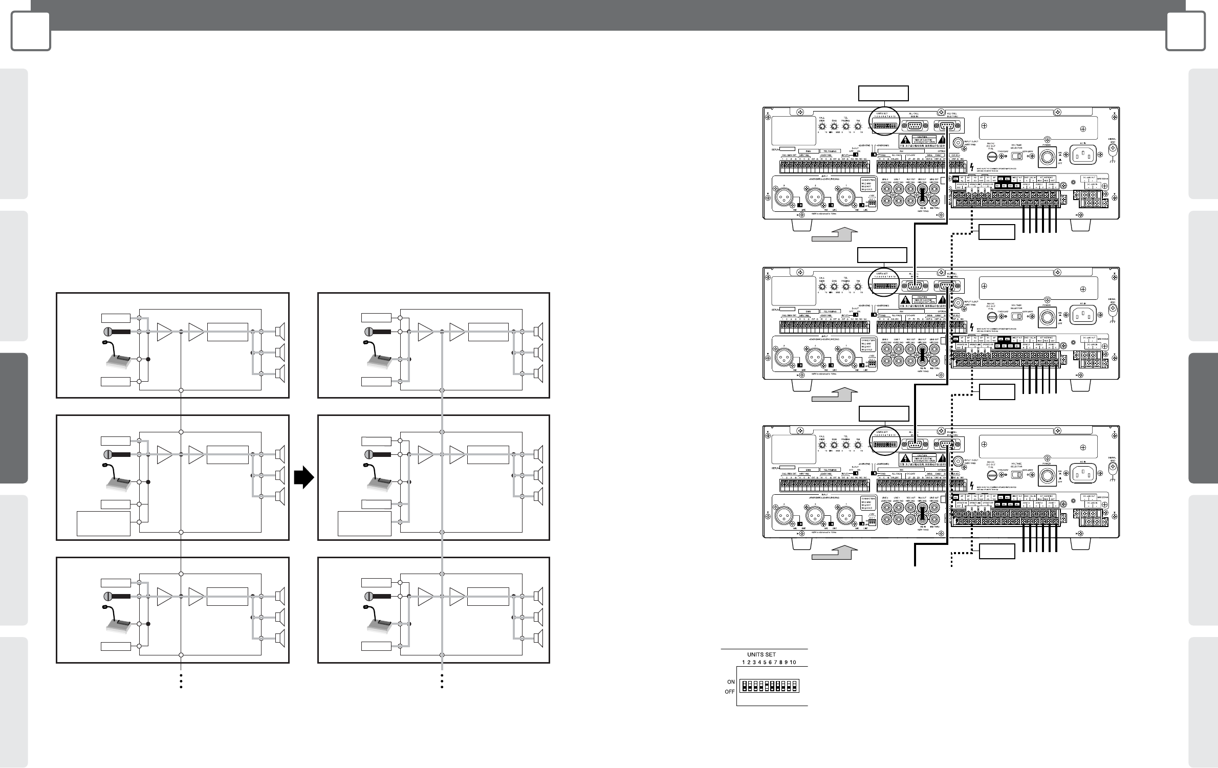
On all of the Amplifiers, set the UNITS SET switches to the total number of Amplifiers.
Example: In the case there is one master and four slaves, set the UNITS SET switches of all of the Amplifiers to 5.
Inter-area All-zone Announcement Connection
• When Amplifiers are being used for separate operation in multiple areas, they can be connected using the ALL CALL BUS to
allow all-zone announcement from one area to all of the other areas.
• The signal paths of an inter-area all-zone announcement during normal operation are shown below. In addition, each input
device that is capable of all-zone announcement has a priority level within the same area and between different areas. During
an emergency announcement from the emergency announcement equipment in Area 2 of the illustration below, for example,
all-zone announcement from any PBX or Remote Microphone from areas 1 through 3 is disabled. When two devices have the
same priority, their input is mixed and announced to all zones. In the illustration below, for example, two PBX or two Remote
Microphones can be used to announce from different areas to all zones.
• Inter-area all-zone announcement can be configured for up to 10 Amplifiers and 10 areas.
BGM
Built-in
Power Amplifier
Microphone
Remote
Microphone
Amplifier
Area 1
Normal operation from individual zone announcement
device (BGM, non-priority microphone)
ALL CALL BUS THRU
ALL CALL BUS THRU
Mixing Mixing
BGM
PBXPBX
BGM
Built-in
Power Amplifier
Microphone
Remote
Microphone
Amplifier
Area 3
ALL CALL BUS THRU
Mixing Mixing
PBX
BGM
Built-in
Power Amplifier
Microphone
Remote
Microphone
Amplifier
ALL CALL BUS IN
ALL CALL BUS IN
BGM
Built-in
Power Amplifier
Microphone
Remote
Microphone
Amplifier
Area 3
ALL CALL BUS THRU
Mixing Mixing
PBX
ALL CALL BUS IN
Area 2
Mixing Mixing
PBX
ALL CALL BUS THRU
BGM
Built-in
Power Amplifier
Microphone
Remote
Microphone
Amplifier
ALL CALL BUS IN
Area 2
Mixing Mixing
PBX
Built-in
Power Amplifier
Microphone
Remote
Microphone
Amplifier
Area 1
ALL CALL BUS THRU
Mixing Mixing
Up to 10 Amplifiers, 10 areas Up to 10 Amplifiers, 10 areas
Inter-area all-zone announcement from all-zone
announcement device (priority microphone and remote
control microphone, PBX, non-priority announcement device)
Emergency
Announcement
Equipment
Emergency
Announcement
Equipment
Important 2:
Connect when you want operation control activated on all of the Amplifiers. For the connection shown in the illustration here, entering the
operation mode on the master also puts all of the slaves into the operation mode as well. Note, however, that the slaves must be in the standby
mode before the master goes into the operation mode.
For information about operation on/off control, see page 24.


