


6
RQT7364
Before use
Connections
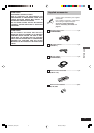
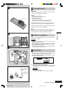
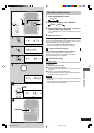
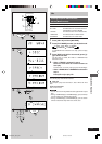
2 Connect the AM loop antenna.
Stand the antenna up on its base. Keep loose antenna cord
away from other wires and cords.
3 Connect the speaker cords.
Confirm the colors of the tags on the ends of the cords.
For White tags:
Connect cords to gray terminals.
For Blue, Black and Red tags:
Connect cords so tag colors match the terminal colors.
Cords with white and blue tags are for high frequency.
Cords with red and black tags are for low frequency.
Incorrect connection can damage the unit.
Caution
Use only the supplied speakers.
The combination of the main unit and speakers provide the
best sound. Using other speakers can damage the unit and
sound quality will be negatively affected.
Caution
• Use the speakers only with the recommended system.
Failure to do so may lead to damage to the amplifier and/
or the speakers, and may result in the risk of fire. Consult
a qualified service person if damage has occurred or if
you experience a sudden change in performance.
• Do not attach these speakers to walls or ceilings.
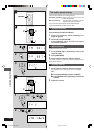
4 Connect the AC power supply cord.
Note
The included AC power supply cord is for use with this unit
only. Do not use it with other equipment.
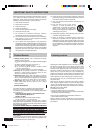
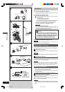
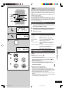
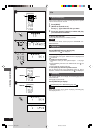
Optional antenna connections
You may need an outdoor antenna if you use this system in a
mountainous region or inside a reinforced-concrete building, etc.
A FM outdoor antenna
Disconnect the FM indoor antenna if an FM outdoor antenna is
installed.
Note
An outdoor antenna should be installed by a qualified technician only.
B AM outdoor antenna
Connect the outdoor antenna without removing the AM loop
antenna. Run 5 to 12 m of vinyl-covered wire horizontally along
a window or other convenient location.
Note
When the unit is not in use, disconnect the outdoor antenna to
prevent possible damage that may be caused by lightning.
Never use an outdoor antenna during a lightning storm.
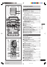
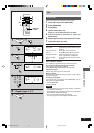
External unit connections
• Make sure that the power supply for all components has been
turned off before making any connections.
• For details, refer to the operating instructions of the unit which
is to be connected.
• All peripheral components and cables sold separately.
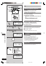
C Connecting analog equipment
This example shows how to connect an analog player with a
PHONO OUT/LINE OUT switch.
When units other than those described are to be connected,
please consult your audio dealer.
Note
• Only an analog player with a built-in phono equalizer can be connected.
• Set the switch to the “LINE OUT” position at the back of the analog
player.
2
AM ANT
FM ANT
EXT
LOOP
75
AM loop antenna
34
R
L
HIGH (6
)
LOW (6
)
Red (+)
Gray (+)
Blue (–)
Black (–)
White
Blue
Red
Black
a
b
1
3
2
To household
AC outlet
AM ANT
FM ANT
EXT
LOOP
75
FM outdoor antenna
(not included)
AM ANT
FM ANT
EXT
LOOP
75
AM outdoor antenna
(not included)
AM loop antenna
(included)
5-12 m
AUX
(L)
(R)
Analo
g
pla
y
er (not included)
“LINE OUT”
position
Rear panel of this unit
R L
RQT7364-P_05-08_EN 30/12/03, 10:34 am6