


CQ-C7405W Installation Instructions YFM294C092CA
(1)
OPENDISPBAND
CQ-C7405W
TILT/SET/APM
SQ
MENU
TUNE
TRACK
MUTE
SBC
-
SW
FOLDER/P
-
SET/DISC
LIST
SOURCE
PWR
/
V
O
L
P
U
S
H
S
E
L
/
S
R
S
W
O
W
D
・
M
4
e
w
TEXT
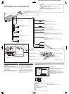
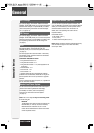
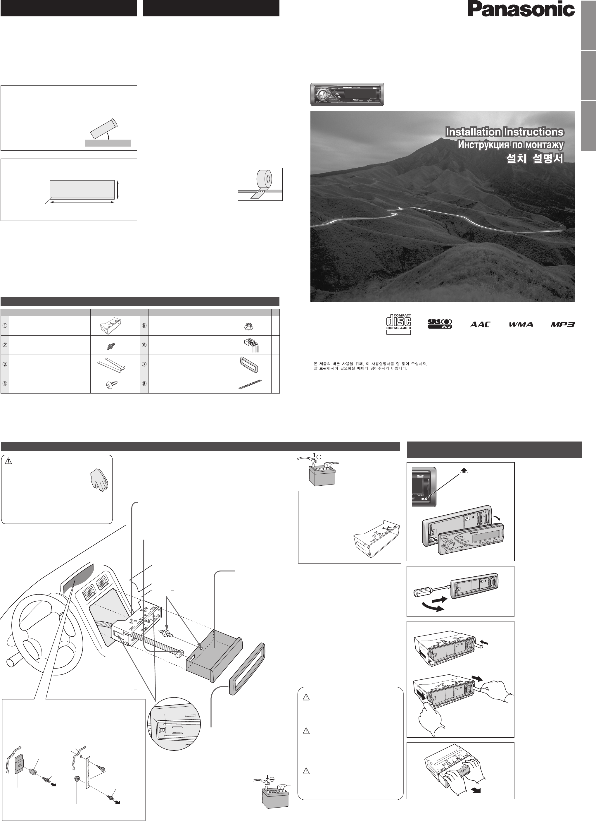
How to install the unit/ä‡Í ÒÏÓÌÚËÓ‚‡Ú¸ ÔË·Ó/
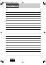
Installation/åÓÌÚ‡Ê/
Mounting collar q insertion. Bend mounting tabs.
ÇÒÚ‡‚ÎÂÌË ÏÓÌÚ‡ÊÌÓÈ ‡Ï˚ q.ᇄ˷‡˛Ú ÏÓÌÚ‡ÊÌ˚ ·ÔÍË.
q
Connection of power connector y
èÓ‰ÒÓ‰ËÌÂÌË ÒËÎÓ‚Ó„Ó ‡Á˙Âχ y
y
5
Tr im plate u mounting
ìÒÚ‡Ìӂ͇ Ó·‡ÏÎÂÌËfl u
u
6
Battery cable reconnection
èÓ‚ÚÓÌÓ ÔÓ‰ÒÓ‰ËÌÂÌË ͇·ÂÎfl Í ·‡Ú‡ÂÂ
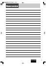
How to remove the unit/ä‡Í ÒÌflÚ¸ ÔË·Ó/
Cautions
● Wear gloves for safety.
●
Make sure that wiring is completed
before installation.
ÇÌËχÌËÂ
● ëΉÛÂÚ Ì‡‰ÂÚ¸ Ô˜‡ÚÍË ‰Îfl
·ÂÁÓÔ‡ÒÌÓÒÚË.
● ëΉÛÂÚ Û·Â‰ËÚ¸Òfl, ˜ÚÓ ÏÓÌÚ‡Ê
˝ÎÂÍÚÓÔÓ‚Ó‰ÓÍ Á‡‚¯ÂÌ ‰Ó
ÏÓÌڇʇ ÔË·Ó‡.
●
●
Remove the cable from the battery negative terminal.
éÚÒÓ‰ËÌfl˛Ú ͇·Âθ ÓÚ ÓÚˈ‡ÚÂθÌÓ„Ó ‚˚‚Ó‰‡ ·‡Ú‡ÂË.
Bend appropriate tabs to secure the unit
without backlash.
ᇄ˷‡ÌËÂÏ ÒÓÓÚ‚ÂÚÒÚ‚Û˛˘Ëı ·ÔÓÍ ÙËÍÒËÛ˛Ú
ÔË·Ó ·ÂÁ Á‡ÁÓ.
q Screw the mounting bolt w into the main unit.
w Secure to the fire wall.
e
Snap the right and left springs into each hole.
q ᇂÂÚ˚‚‡˛Ú mÓÌÚ‡ÊÌ˚È ·ÓÎÚ w ‚„·‚Ì˚È ·ÎÓÍ.
w äÂÔÎÂÌËÂ Í ÚÂÔÎÓËÁÓÎflˆËÓÌÌÓÈ Ô‡ÌÂÎË.
e
Ç‚Ó‰flÚ Ô‡‚Û˛ Ë ÎÂ‚Û˛ ÔÛÊËÌ˚ ‚ ÓÚ‚ÂÒÚËfl ÔÓ‰ ÌËı.
q w
w
e
Main unit securing
äÂÔÎÂÌË „·‚ÌÓ„Ó
·ÎÓ͇
4
Securing to fire wall
äÂÔÎÂÌËÂ Í ÚÂÔÎÓËÁÓÎflˆËÓÌÌÓÈ Ô‡ÌÂÎË
Using the rear support strap i
ë ÔÓÏÓ˘¸˛ Á‡‰ÌÂÈ ÓÔÓÌÓÈ Ô·ÌÍË i
i
Using the rubber bushing (Option)
ë ÔÓÏÓ˘¸˛ ÂÁËÌÓ‚ÓÈ ‚ÚÛÎÍË (ÔÓ ÓÔˆËË)
3mm
Tapping screw r
ë‡ÏÓ̇ÂÁ‡˛˘ËÈ ‚ËÌÚ r
r
To the unit
ä ÔË·ÓÛ
To the unit
ä ÔË·ÓÛ
Rear support strap i
ᇉÌflfl ÓÔÓ̇fl Ô·Ì͇ i
i
Hexagonal nut t
òÂÒÚË„‡Ì̇fl „‡È͇ t
t
Rear support bracket
(supplied with car)
ᇉÌËÈ ÓÔÓÌ˚È ÍÓ̯ÚÂÈÌ
(ÔÓÒÚ‡‚ÎflÂÏ˚È Ò ‡‚ÚÓÏÓ·ËÎÂÏ)
Rubber Bushing (Option)
êÂÁËÌÓ‚‡fl ‚ÚÛÎ͇ (ÔÓ ÓÔˆËË)
Mounting Bolt w
åÓÌÚ‡ÊÌ˚È ·ÓÎÚ w
w
Caution
When this unit is installed in dashboard,
ensure that there is sufficient air flow
around the unit to prevent damage from
overheating, do not block any ventilation
holes on the unit.
ÇÌËχÌËÂ
èË ÏÓÌڇʠ̇ÒÚÓfl˘Â„Ó ÛÒÚÓÈÒÚ‚‡ ̇ Ô‡ÌÂθ
ÔË·ÓÓ‚ ÒΉÛÂÚ Ó·ÂÒÔ˜ËÚ¸ ‰ÓÒÚ‡ÚÓ˜Ì˚È ÔÓÚÓÍ
‚ÓÁ‰Ûı‡ ‚ÓÍÛ„ ÌÂ„Ó ‚Ó ËÁ·ÂʇÌË „Ó
ÔÓ‚ÂʉÂÌËfl ËÁ-Á‡ Ô„‚‡, Ô˘ÂÏ ÌÂ
ÒΉÛÂÚ Á‡Í˚‚‡Ú¸ ‚ÂÌÚËÎflˆËÓÌÌ˚ ÓÚ‚ÂÒÚËfl
ÛÒÚÓÈÒÚ‚‡.
Mounting Bolt w
åÓÌÚ‡ÊÌ˚È ·ÓÎÚ w
w
Remove the face plate.
ëÌËχ˛Ú ÎËˆÂ‚Û˛ Ô‡ÌÂθ
ÔË·Ó‡.
1
Remove the trim plate u.
ëÌËχ˛Ú Ó·‡ÏÌÂÌËÂ
u.
u
2
3
Pull out the unit with
both hands.
Ç˚Ú‡ÒÍË‚‡˛Ú Ó·ÂËÏË
Û͇ÏË ÔË·Ó.
4
Clank!
1
2
3
4
4
4
5
6
q
4
Lock release
q Insert the lock cancel plate
e until you hear a click.
w Pull the main unit.
ëÌflÚË ÒÚÓÔÓÂÌËfl
q ÇÒÚ‡‚Îfl˛Ú Ô·ÒÚËÌÛ ÒÌflÚËfl
ÒÚÓÔÓÂÌËfle‰Ó ˘ÂΘ͇.
w TflÌËÚe „Îa‚ÌÛ˛ e‰ËÌˈÛ.
q
e
w
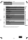
0 – 30°
53 mm
182 mm
4.5 mm – 6.0 mm
AAC WMA MP3 CD Player/Receiver
AAC WMA MP3 CD-ÔÎÂÂ/ÂÒË‚Â
Model: CQ-C7405W
●Please read these instructions carefully before using this product and keep this manual for future reference.
●è‰ ̇˜‡ÎÓÏ ˝ÍÒÔÎÛ‡Ú‡ˆËË ÔÓÒËÏ ÔÓ˜ËÚ‡Ú¸ ̇ÒÚÓfl˘Û˛ ËÌÒÚÛÍˆË˛ ‚ÌËχÚÂθÌÓ Ë ı‡ÌËÚ¸  ̇ ÔÓθÁÓ‚‡ÌË ̇ ·Û‰Û˘ÂÂ.
●
YFM294C092CA NY1006-1116 Printed in China
Matsushita Electric Industrial Co., Ltd.
Web Site: http://panasonic.net
Consult a professional for installation.
●Verify the radio using the antenna and speakers before installation.
èÓ ‚ÓÔÓÒÛ ÏÓÌڇʇ ÒΉÛÂÚ Ó·‡˘‡Ú¸Òfl Í ÒÔˆˇÎËÒÚÛ.
●è‰ ÏÓÌÚ‡ÊÓÏ ÔÓ‚Âfl˛Ú ‡‰ËÓÔËÂÏÌËÍ Ò ÔÓÏÓ˘¸˛
‡ÌÚÂÌÌ˚ Ë „ÓÏÍÓ„Ó‚ÓËÚÂÎÂÈ.
●
●Mounting angle side to side : horizontal
front to rear : 0 – 30°
●ì„ÓÎ ÏÓÌڇʇ ‚ ÔÓÔ˜ÌÓÈ ÔÎÓÒÍÓÒÚË : ÉÓËÁÓÌڇθ
‚ ÔÓ‰ÓθÌÓÈ ÔÎÓÒÍÓÒÚË : 0–30°
●
°
●Mounting space
●èÎÓ˘‡‰¸ ÔÓ‰ ÏÓÌÚ‡Ê
●
Before Installation/è‰ ÏÓÌÚ‡ÊÓÏ/
Before Wiring/è‰ ÏÓÌÚ‡ÊÓÏ ˝ÎÂÍÚÓÔÓ‚Ó‰ÓÍ
/
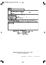
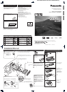
Supplied Hardware/ÑÂÚ‡ÎË, ‚ıÓ‰fl˘Ë ‚ ÍÓÏÔÎÂÍÚ‡ˆË˛ ÔÓÒÚ‡‚ÍË/
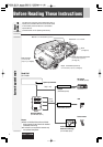
Exclusively operated with 12 V battery with
negative (–) ground.
Connect the power lead (red) last.
Connect the battery lead (yellow) to the positive (+) terminal of
the battery or fuse block terminal (BAT).
Strip about 5 mm of the lead ends for connection.
Apply insulating tape to bare leads.
Secure loosened leads.
ꇷÓÚ‡ÂÚ ÚÓθÍÓ Ò ÔËÚ‡ÌËÂÏ ÓÚ 12 V {B} ·‡Ú‡ÂË
Ò ÓÚˈ‡ÚÂθÌÓÈ (–) ÁÂÏÎÂÈ.
èÓ‰ÒÓ‰ËÌfl˛Ú ÒËÎÓ‚ÓÈ ‚˚‚Ó‰ÌÓÈ ÔÓ‚Ó‰ (͇ÒÌ˚È) ÔÓÒΉÌËÏ.
èÓ‰ÒÓ‰ËÌfl˛Ú ‚˚‚Ó‰ÌÓÈ ÔÓ‚Ó‰ (ÊÂÎÚ˚È) Í ÔÓÎÓÊËÚÂθÌÓÏÛ (+) ‚˚‚Ó‰Û
·‡Ú‡ÂË ËÎË ÍÎÂÏÏ ·ÎÓ͇ Ô·‚ÍËı Ô‰Óı‡ÌËÚÂÎÂÈ (BAT).
ë ÍÓ̈ӂ ‚˚‚Ó‰Ì˚ı ÔÓ‚Ó‰Ó‚ ÒÌËχ˛Ú ËÁÓÎflˆË˛ ̇ ‰ÎËÌ ÓÍÓÎÓ 5
mm {ÏÏ} ‰Îfl ÒÓ‰ËÌÂÌËfl.
ç‡ Ó·Ì‡ÊÂÌÌ˚ ‚˚‚Ó‰Ì˚ ÔÓ‚Ó‰‡
̇Í·‰˚‚‡˛Ú ËÁÓÎflˆËÓÌÌÛ˛ ÎÂÌÚÛ.
îËÍÒËÛ˛Ú ÓÒ··ÎÂÌÌ˚ ‚˚‚Ó‰Ì˚ ÔÓ‚Ó‰‡.
–
EnglishêÛÒÒÍËÈ
* w, e, r and t consist of a set. (YEP0FZ5739) * w, e, r Ë t ÒÓÒÚ‡‚Îfl˛Ú ÍÓÏÔÎÂÍÚ. (YEP0FZ5739)
* w, e, r t (YEP0FZ5739)
Remove mounting collar q and trim plate u from the main
unit temporarily, which are already mounted at shipment.
ÇÂÏÂÌÌÓ ÒÌËχ˛Ú Ò „·‚ÌÓ„Ó ·ÎÓ͇ ÔË·Ó‡ ÏÓÌÚ‡ÊÌÛ˛ ‡ÏÛ q Ë
Ó·‡ÏÎÂÌË u, ÒÏÓÌÚËÓ‚‡ÌÌ˚ ÔË ÓÚ„ÛÁÍÂ.
q u
Snapping point
MoÏeÌÚaθÌ˚È cÌËÏoÍ
ÔÛÌÍÚa
q
w
q
w
1
No.
Diagram
Q'ty
Item No. Diagram
Q'ty
Item
Mounting collar
åÓÌÚ‡Ê̇fl ‡Ï‡
Mounting bolt (5 mmø)
åÓÌÚ‡ÊÌ˚È ·ÓÎÚ (5 mm {ÏÏ} ø)
ø
Power connector
ëËÎÓ‚ÓÈ ‡Á˙ÂÏ
Hex. Nut (5 mm ø)
òÂÒÚË„‡Ì̇fl „‡È͇ (5mm{ÏÏ} ø)
ø
Tr im plate
é·‡ÏÎÂÌËÂ
Rear support strap
ᇉÌflfl ÓÔÓ̇fl Ô·Ì͇
Tapping Screw (5 mm ø x 16 mm)
ë‡ÏÓ̇ÂÁ‡˛˘ËÈ ‚ËÌÚ (5mm{ÏÏ} ø x 16 mm)
ø x 16mm
FX0214C384ZB ✽
✽
✽
✽
Lock cancel plate
è·ÒÚË̇ ÒÌflÚËfl ÒÚÓÔÓÂÌËfl
YFG044C002ZA
1
2
1
1
1
1
1
YEFC051013
YGAJ021011
e
w
q