


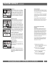
In the Custom Settings mode all of the outlet
delays as well as the trigger sources for each individ-
ual bank operate from the configuration that has been
programmed into the EEPROM of the unit through
the communication interface on the rear panel. Refer
to the section titled “Max Pro Series
Communication/Configuration Specifications” for
complete details on configuring this mode of opera-
tion.
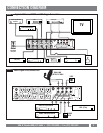
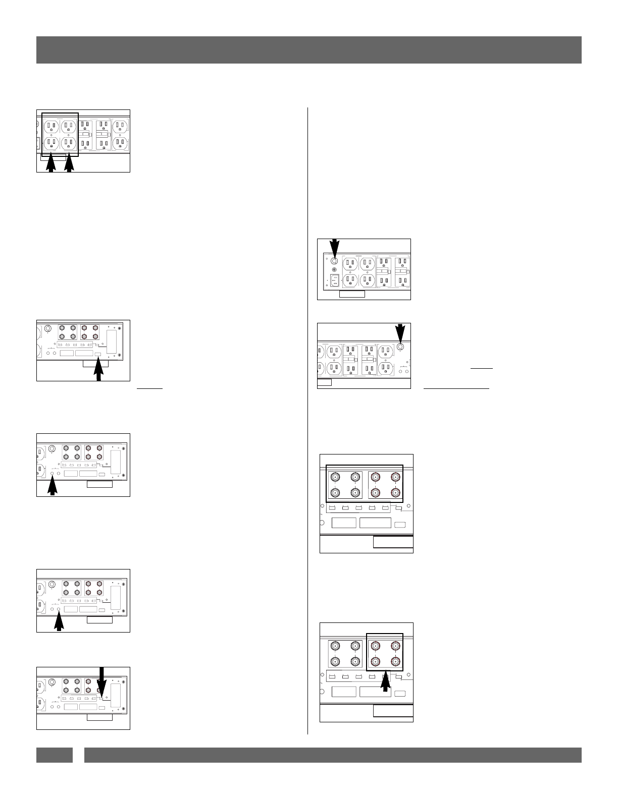
Circuit Breakers:
There are two separate circuit breakers on the back
panel of the MAX 7500-Pro. The main circuit
breaker will trip only if the total current draw
exceeds the maximum current rating (15A). This
means that collectively, all outlets must draw more
than 15 Amps before the circuit breaker will trip.
There is also a 6 Amp circuit breaker to protect
the 720 VA Isolation Transformer and its circuitry.
The Isolation Transformer provides pure power for
digital source components, which require very little
current to operate at peak performance.
Please note:
Do not
plug high-powered
amplifiers or powered subwoofers into the
Bank 3 or 4 Outlets
. Their current require-
ments may exceed the 6 Amp limit and
cause the circuit breaker to trip.
Coaxial Line Protection:
All coaxial cable sheaths from outdoors must
be grounded to the building grounding elec-
trode system where they enter the building
(per applicable NEC/CEC code). A driven
ground rod is not adequate.
Panamax's exclusive SignalPerfect™ Technology
provides application specific protection for your
satellite and cable TV equipment. The satellite
connections are for coaxial cables connected to a
DBS (single or dual LNB) satellite dish. The CATV
connection is for a non-amplified rooftop antenna or
cable TV line. Alternatively, it may be used to protect
the equipment plugged into the MAX 7500-Pro from
"backdoor" surges in situations where the video
signal is run to another room for a 2nd television.
Cable TV (Including HDTV) & Cable Modems:
TV tuners operate at approximately 500 millivolts
(1/2 volt) and utilize the frequency spectrum of 50
MHz to 950 MHz. Digital cable boxes and cable
modems typically operate at slightly higher voltages
while cable modems utilize the frequency range
below 50 MHz. The clamping level of the MAX
7500-Pro's CATV protection circuitry is 1400 milli-
volts (1.4 volts). The circuitry is shielded to prevent
interference and has been optimized to have less than
1dB of signal loss throughout the entire frequency
range up to 950 MHz.
FEATURE DETAILS
(continued)
Banks 1 and 2 Regulated Outlets:
Two individually switched banks are fed through
separate “Balanced Double L” noise filtration circuits.
These circuits are designed to eliminate the AC con-
tamination that is most detrimental to the perform-
ance of analog or video components like stereo
receivers, VCRs or televisions. The two dedicated
filters are carefully engineered to provide power fil-
tration and inter-component "noise isolation" for both
"common-mode" (line/neutral-to-ground) and "nor-
mal-mode" (line-to-neutral) EMI/RFI. This means
that high-frequency interference will be drastically
reduced not only from the incoming power but also
from equipment plugged into the other outlet banks,
regardless of what "mode" it occurs in. Even equip-
ment with ungrounded, 2-blade plugs, receives clean
power.
Convenience Lamp:
The convenience lamp included with your MAX
®
7500-Pro plugs into an industry standard USB jack on
the rear panel. Its purpose is to provide better visibility
of other components and their A/V connections during
system setup. Warning: The USB jack only provides
power. The lamp will be ON whenever it is plugged in.
DO NOT
use this jack for other USB devices.
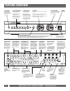
DC Triggers:
Input Trigger:
This feature provides an ON/OFF trigger for the MAX
7500-Pro using a DC voltage control signal. Many
components such as pre-amplifiers and receivers
have a 12VDC trigger built-in, and will transmit a
constant power signal when turned on and in use.
This power signal will initiate the startup or shut-
down sequence of the MAX 7500-Pro outlet banks.
An AC adapter of the appropriate voltage, plugged
into a switched outlet on the receiver, may also be
used if a 12V trigger is not built in.
Output Trigger:
The MAX 7500-Pro generates its own 12VDC remote
signal to control other components. In its default
state, this output turns ON ten seconds after the Input
Trigger receives a signal and OFF when the input
trigger signal is turned off. This output also uses a
standard 3.5mm mono mini-plug jack.
Modes of Operation:
The MAX 7500-Pro offers two modes of operation
selected using the “Switch Settings/Custom Settings”
switch. In the Switch Settings mode all of the out-
let delays are configured for either Always On or
Delayed operation using the five two-position slide
switches.
USA & Canada (800) 472-5555 • (707) 283-5900 • Fax (707) 283-5901
6
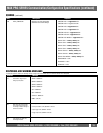
BANK 1 ALWAYS ON BANK 2 SWITCHED BANK 3 SWITCHED BANK 4 SWITCHED BANK 5 HIGH CURRENT
T BREAKER
20VAC/15A
HC 1
SWITCHE
HC 2
SWITCHE
12 AMP MAX
6 AMP MAX
REGULATED
15 AMP MAX
REGULATED & ISOLATED FOR HD VIDEO
SUB
AMP
RECEIVER
DVR &
DIGITAL
RADIO
HD CABLE
HD SAT
TEST MONTHLY
SEE INSTRUCTIOS
TEST MONTHLY
SEE INSTRUCTIOS
TEST RESET
RESET TEST
RESET TEST
TEST RESET
6 AMP MAX
GH CURRENT
HD
SATELLITE
SATELLITE 1
SATELLITE 2
HD
CATV / ANT
CABLE 1
CABLE 2
HC 1
SWITCHED
HC 2
SWITCHED
CIRCUIT BREAKER
BANKS 3 AND 4
PHONE LINE
TO EQUIP 2
PHONE LINE
TO EQUIP 1
PHONE
LINE IN
LAN
LINE IN
LAN
TO EQUIP
USB LIGHT
INPUT
3-24VDC
OUTPUT
12V/400mA
BANK 2 BANK 3 BANK 4 5 HC 1 5 HC 2
SWITCH
SETTINGS
CUSTOM
SETTINGS
DELAY
ALWAYS
ON
DELAY
ALWAYS
ON
DELAY
ALWAYS
ON
DELAY
ALWAYS
ON
DELAY
ALWAYS
ON
COMMUNICATION INTERFACE
5VDC/100mA
TRIGGER
MP MAX
RECEIVER
RENT
HD
SATELLITE
SATELLITE 1
SATELLITE 2
HD
CATV / ANT
CABLE 1
CABLE 2
HC 1
SWITCHED
HC 2
SWITCHED
CIRCUIT BREAKER
BANKS 3 AND 4
PHONE LINE
TO EQUIP 2
PHONE LINE
TO EQUIP 1
PHONE
LINE IN
LAN
LINE IN
LAN
TO EQUIP
USB LIGHT
INPUT
3-24VDC
OUTPUT
12V/400mA
BANK 2 BANK 3 BANK 4 5 HC 1 5 HC 2
SWITCH
SETTINGS
CUSTOM
SETTINGS
DELAY
ALWAYS
ON
DELAY
ALWAYS
ON
DELAY
ALWAYS
ON
DELAY
ALWAYS
ON
DELAY
ALWAYS
ON
COMMUNICATION INTERFACE
5VDC/100mA
TRIGGER
CEIVER
BANK 1 ALWAYS ON BANK 2 SWITCHED BANK 3 SWITCHED BANK 4 SWITCHED
GROUND
LUG
15 AMP CIRCUIT BREAKER
MAIN POWER 120VAC/15A
12 AMP MAX
6 AMP MAX
REGULATED
REGULATED & ISOLATED FOR HD VIDEO
DVR &
DIGITAL
RADIO
HD CABLE
HD SAT
TEST MONTHLY
SEE INSTRUCTIOS
TEST MONTHLY
SEE INSTRUCTIOS
TEST RESET
RESET TEST
RESET TEST
TEST RESET
6 AMP MAX
WAYS ON BANK 2 SWITCHED BANK 3 SWITCHED BANK 4 SWITCHED BANK 5 HIGH CURRENT
HC 1
SWITCHED
HC 2
SWITCHED
CIRCUIT BREAKER
BANKS 3 AND 4
INPUT
3-24VDC
OUTPUT
12V/400mA
AL
TRIGGER
12 AMP MAX
6 AMP MAX
REGULATED
15 AMP MAX
REGULATED & ISOLATED FOR HD VIDEO
SUB
AMP
RECEIVER
DVR &
DIGITAL
RADIO
TEST MONTHLY
SEE INSTRUCTIOS
TEST MONTHLY
SEE INSTRUCTIOS
TEST RESET
RESET TEST
RESET TEST
TEST RESET
6 AMP MAX
HD
SATELLITE
SATELLITE 1
SATELLITE 2
HD
CATV / ANT
CABLE 1
CABLE 2
PHONE LINE
TO EQUIP 2
PHONE LINE
TO EQUIP 1
PHONE
LINE IN
LAN
LINE IN
LAN
TO EQUIP
USB LIGHT
UTPUT
V/400mA
BANK 2 BANK 3 BANK 4 5 HC 1 5 HC 2
SWITCH
SETTINGS
CUSTOM
SETTINGS
DELAY
ALWAYS
ON
DELAY
ALWAYS
ON
DELAY
ALWAYS
ON
DELAY
ALWAYS
ON
DELAY
ALWAYS
ON
5VDC/100mA
R
HD
SATELLITE
SATELLITE 1
SATELLITE 2
HD
CATV / ANT
CABLE 1
CABLE 2
PHONE LINE
TO EQUIP 2
PHONE LINE
TO EQUIP 1
PHONE
LINE IN
LAN
LINE IN
LAN
TO EQUIP
USB LIGHT
UTPUT
V/400mA
BANK 2 BANK 3 BANK 4 5 HC 1 5 HC 2
SWITCH
SETTINGS
CUSTOM
SETTINGS
DELAY
ALWAYS
ON
DELAY
ALWAYS
ON
DELAY
ALWAYS
ON
DELAY
ALWAYS
ON
DELAY
ALWAYS
ON
5VDC/100mA
R