


17
Model 970 7.1 Channel Preamplifier Processor
Owner’s Manual
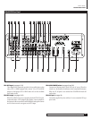
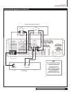
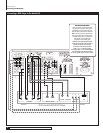
Connecting Your Model 970
Component
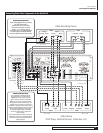
If your DVD player has component video outputs, connect them
to the component DVD IN jacks (
RP1
). Because component video connections
require three video-grade cables, remember to follow the alphabet (“Y” to “Y,”
“P
B
” to “P
B
,” and “P
R
” to “P
R
”) when making these connections.
DVI/HDMI
If your DVD player has a DVI or HDMI video output and your video
monitor has a DVI or HDMI input, connect the DVD player to the Model 970’s
DVI 1 or 2 input (
RP21
). (For HDMI-equipped DVD players, use an HDMI-to-DVI
adapter, or dual-purpose cable such as those available from Outlaw Audio.)
Audio Connections
Analog
Using a pair of RCA-to-RCA audio cables, connect your DVD player’s L
and R channel analog audio outputs to the DVD analog audio jacks (
RP5
).
Digital
Connect your DVD player’s digital audio output (coaxial or optical)
to one of the digital inputs (
RP12
). Note the selected input on your worksheet
for configuration later.
Multi-Channel Audio
If your DVD player has a multi-channel audio output for
DVD-Audio or SACD playback, connect the six outputs from your player to the
multi-channel AUDIO IN jack set (
RP5
). Use the L, R, CEN, SUB, SL, and SR
jacks only – ignore the jacks labeled SBL and SBR. (These will accommodate
future 7.1-channel formats if they appear.) Be careful to maintain continuity:
Connect L to L, center to CEN, and so on. If your DVD player includes a built-in
Dolby Digital decoder with 5.1-channel analog audio outputs but no DVD-A or
SACD capability, do not use the player’s 5.1 channel analog outputs. Instead, use
a digital connection as described above. Your ears will applaud your choice.
NOTE: You must use the multi-channel audio input for SACD and
DVD-Audio players in order to hear the high-resolution digital sound
these players provide.
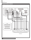
Video Recorder
You can connect a video recording device (VCR, PVR, DVD recorder, etc.) by
using the following methods.
Video Connections
Composite
Connect your video recorder’s composite video output to the VIDEO
1 IN composite video input jack (
RP16
). Then connect the recorder’s composite
video input to the VIDEO 1 REC OUT composite video jack (
RP16
). Use the same
type of cable specified in the DVD Player section immediately above.
S-Video
Using a S-video cable with a small 4-pin mini-DIN connector at
each end, connect the DVD player’s S-video output to the S-video Video 1
input (
RP16
). Then connect the recorder’s S-video input to the S-video Video
1 output (
RP16
).
Audio Connections
Digital
Connect your video recorder’s digital audio output (coaxial or optical)
to one of the digital inputs (
RP12
). Note the selected input on your worksheet
for configuration later.
If your recording device has a digital input, connect it to either the coaxial or
optical (
RP14
) output jack. The signal from a selected digital source will be
sent to the recorder.
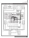
Digital TV Tuner/Cable Box/Satellite Receiver
Video Connections
Composite
Using a video cable with yellow RCA jacks at both ends, connect
the device’s composite video output to your choice of the Video 1-3 composite
video inputs. (
RP16
or
RP17
).
S-Video
Using an S-video cable, connect the device’s S-video output to your
choice of the Video 1-3 S-video inputs. (
RP16
or
RP17
).
Component
If your device has component video outputs, connect them to the
component Video 1-2 input jacks (
RP1
). As you make this connection, remember
to “follow the alphabet.” (See DVD player above if you don’t remember what
this means.)
DVI/HDMI
If your device a DVI or HDMI video output and your video monitor
has a DVI or HDMI input, connect the device to the DVI 1 or 2 input (
RP21
).
(For HDMI-equipped components, use either an interconnect cable with one
type of connector on each end [preferred] or an HDMI-to-DVI adapter.)
Audio Connections
Analog
Using a pair of RCA-to-RCA audio cables, connect your device’s L and
R channel analog audio outputs to the Video 1-3 analog audio jacks (
RP16
or
RP17
).
Digital
Connect your device’s digital audio output (coaxial or optical) to one
of the digital inputs (
RP12
). Note the selected input on your worksheet for
configuration later.
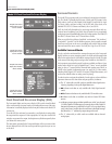
NOTE: Particularly with digital cable set top boxes, we recommend that
you make both an analog and digital audio connections. This will enable
the Model 970 to revert to analog audio when you switch away from a
digital channel to one that only has analog audio. (See page 19)
Video Display Connections
Connect a video display device (a TV, projector, etc.) to the Model 970 using
the following methods.
Video Connections
Composite
Using a video cable with yellow RCA jacks at both ends, connect
the display device’s composite video input to the Model 970’s composite Monitor
Out jack (
RP18
).
S-Video
Using an S-video cable, connect the display device’s S-video input to
the S-Video Monitor Out jack (
RP18
).
Component
If your display device has component video inputs, connect them to
the component Monitor Out jacks (
RP4
). Once again, “follow the alphabet.”
DVI/HDMI
If your display device has a DVI or HDMI video input, connect it
to the DVI Out connection (
RP22
). (For HDMI-equipped components, use an
HDMI-to-DVI adapter.)
NOTE: The Model 970's on-screen display does not appear at the DVI
OUT jack. Use a component, S-Video, or composite video connection
to your video display device in addition to the DVI connection.