


9
5. Cut the loop at the end of the
blue/white
AMP
REMOTE
TURN
ON
wire, strip about
1
/
2
inch of
insulation from its end, then con-
nect it to any optional equip-
ment, designed to run from a
switched source, that you want
the stereo to turn on and off
(such as a booster or a power
antenna).
This wire does not provide
power to the components. It sim-
ply turns them on or off. If you do
not use this wire, secure it with a
wire tie and do not let its bare
wire ends touch metal.
Connecting Speakers
1. Connect the gray wire to the
right speaker’s positive termi-
nal. This terminal is usually
marked with a plus (+) sign or
red mark.
2. Connect the gray/black wire to
the right speaker’s negative ter-
minal. This terminal might be
marked with a minus (
–
) sign or
it might not be marked at all.
3. Connect the white wire to the left
speaker’s positive terminal.
4. Connect the white/black wire to
the left speaker’s negative termi-
nal.
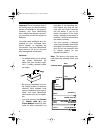
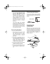
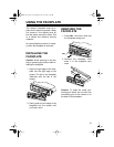
Connecting the Antenna
Connect the vehicle’s antenna cable
to the antenna jack on the back of the
stereo.
Completing the
Connections
Make sure you have securely made
all other connections, then plug the
harness’ connector into the stereo’s
14-pin wiring socket. Reconnect the
cable to the vehicle’s negative (–)
battery terminal.
Vehicle
'
s Antenna
Antenna
Connector
Back of Stereo
Back of Stereo
Vehicle’s Antenna Cable
12-2114.fm Page 9 Wednesday, July 14, 1999 12:35 PM