9
Before Using
Connections Other Information
Operation
1 Connecting the amplifier
Connect the tuner’s OUTPUT jacks and the amplifier’s TUNER input jacks using the audio connection
cable. Refer to the amplifier’s instruction manual for connection information.
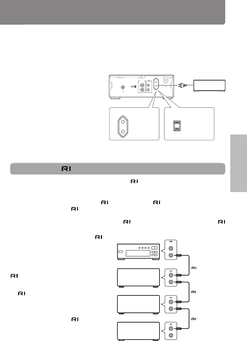
2 AC outlet (UNSWITCHED)
The AC power cord of another
component can be connected to this AC
OUTLET connector.
This means that if the T-405TX is plugged
into an AC outlet, AC power is available
to this AC OUTLET even if the T-405TX is
off.
The shape and capacity of the AC outlet
may differ depending on the area of
purchase. Make sure that the capacity of
other components connected to this unit
does not exceed the capacity that is
printed on the rear panel.
Stereo cassette deck
Amplifier
T-405TX
CD player
Supplied
cable
cable
cable
REMOTE
CONTROL
Connecting the connector
If you are using other ONKYO components equipped with connectors, you can control these compo-
nents using the amplifier‘s remote controller.
Before connecting
• The amplifier must be connected to the
system hookups for control operations.
• Each component has two
connectors. There is no difference between these connectors.
• The components may be connected in any order.
• Remote control operation is not possible if only the
remote control cable is connected to the
connectors. Connect the audio connection cables correctly.
The illustration is an example of an
hookup. With these hookups, you can use
the Program Timer function. (See “Using the
timer” on page 23).
For the Program Timer function, at least the
unit and amplifier must be connected via the
connectors.
Note
An
remote control cable equipped with
a 1/8 in. (3.5mm) diameter miniature two-
conductor phone plug is included with this
unit and with every compact disc player and
cassette deck that bears the
mark.
OUTPUT
L
R
REMOTE
CONTROL
ANTENNA
AC OUTLET
AC 230-240V 50Hz
UNSWITCHED
100W MAX.
75
FM
Capacity is
120 watts.
120 V, 60 Hz models
230-240 V, 50 Hz models
Capacity is
100 watts.


