


12
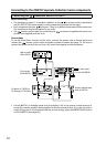
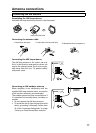
Connecting to the ONKYO Separate Collection Series components
Before connecting
• The hookups on page 11 is needed in addition to the (for remote control operations)
and AC OUTLET (for power supply to each component) hookups on this page.
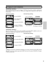
• Each component has two connectors. There is no difference between those connectors.
The components may be connected in any order.
• The remote control cable for connecting the connectors is supplied with each com-
ponent (not supplied with the unit).
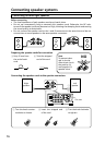
Connections
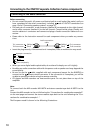
To use the Clock/Timer function of this unit’s, connect the power cord as shown below and
connect the remote control cable and audio connection cables (see page 11). Be sure to
connect the power cord of this unit to an AC outlet that supplies continuous power.
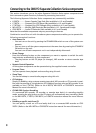
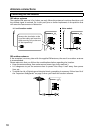
• If the R-805TX is in Standby mode (only the display is lit) in the system, a small amount of
power (for standby mode) is being supplied to the connected devices. If you do not wish to
supply this power to the connected devices to save energy, press the ENERGY SAVE button
on the R-805TX. (See page 20.)
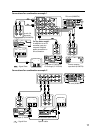
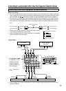
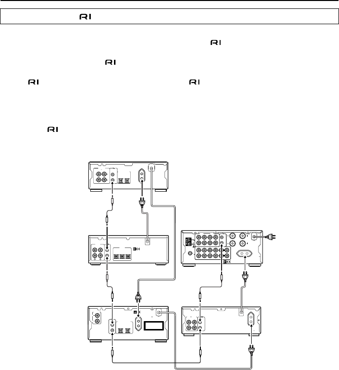
Connecting the connectors and AC OUTLETS
L
R
SPEAKERS
OUT
IN
L
R
OUT
MD
CDR TAPE
CD
IN
LINE/DVD PROCESSOR
OUT
IN
OUT
IN
REMOTE
CONTROL
L
R
L
R
L
R
AM
FM
75
ANTENNA
CAUTION:
SPEAKER
IMPEDANCE
4 OHMS MIN.
/SPEAKER
AC OUTLET
AC 230-240V
50Hz
SWITCHED
100W MAX.
L
R
D
(REC) (PLAY)
INPUT OUTPUT
REMOTE
CONTROL
AC OUTLET
AC 230-240
V 50
Hz
UNSWITCHED
100W MAX
.
OPTICAL
L
R
ANALOG
OUTPUT
AC OUTLET
AC 230-240V 50Hz
UNSWITCHED
100W MAX.
12
DIGITAL OUTPUT
REMOTE
CONTROL
"CLASS 1 LASER
PRODUCT"
L
R
(REC) (PLAY)
INPUT OUTPUT
OPTICAL
INPUT 1 INPUT 2
DIGITAL
L
R
L
K
ANALOG
OUTPUT
REMOTE
CONTROL
L
R
(
REC
)(
PLAY
)
INPUT OUTPUT
REMOTE
CONTROL
OPTICAL
12
DIGITAL INPUT
L
R
ANALOG
Stereo cassette tape
deck (K-505TX)
This unit (R-805TX)
CD recorder
CD player (C-705TX) or
CD changer (C-707CHX)
To wall outlet
MD recorder
(MD-105TX)
(CDR-205TX)