


14
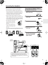
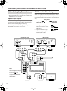
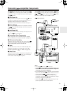
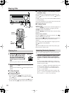
Connecting Your Other Components to the CR-505
• Read the manuals supplied with your components.
• Don’t connect the power cord until you’ve completed and
double-checked all connections.
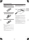
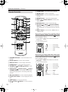
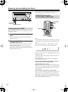
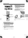
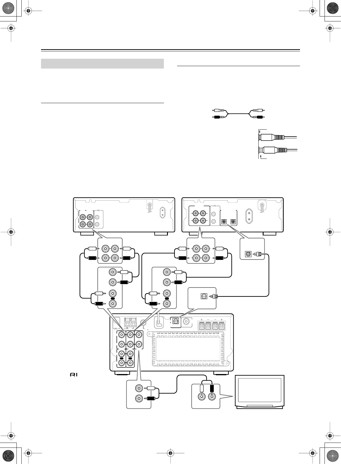
Optical Digital Output
The CD Receiver’s optical digital output has a shutter-type
cover that opens when an optical plug is inserted and closes
when it’s removed. Push a plug in all the way.
Caution:
To prevent shutter damage, hold the optical
plug straight when inserting and removing.
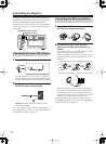
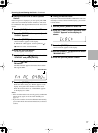
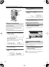
RCA Connection Color Coding
RCA-type connections are usually color coded: red and
white. Use red plugs to connect right-channel audio inputs
and outputs (typically labeled “R”). Use white plugs to con-
nect left-channel audio inputs and outputs (typically labeled
“L”).
• Push plugs in all the way to
make good connections (loose
connections can cause noise or
malfunctions).
• To prevent interference, keep
audio cables away from power
cords and speaker cables.
Before Making Any Connections
Right (red)
Left (white)
Analog audio
Right (red)
Left (white)
Right!
Wrong!
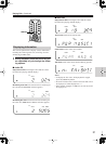
OUT OUT
SPEAKERS
RL
AM
FM
75
ANTENNA
PRE OUT
OPTICAL
DIGITAL
OUT
SUB
WOOFER
IN IN IN
REMOTE
CONTROL
TAPE LINEMD
R
L
R
L
L
R
(REC) (PLAY)
INPUT OUTPUT
REMOTE
CONTROL
L
R
(
REC
)(
PLAY
)
INPUT OUTPUT
REMOTE
CONTROL
OPTICAL
12
DIGITAL INPUT
L
R
ANALOG
L
R
L
R
L
R
(REC) (PLAY)
INPUT
TAPE
IN
OUTPUT
OUT
L
R
(REC) (PLAY)
INPUT
MD
IN
OUTPUT
OUT
L
R
LINE
IN
L
AUDIO OUT
OPTICAL
1
DIGITAL INPUT
OPTICAL
DIGITAL
OUT
L
R
L
R
L
R
R
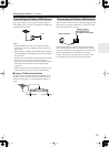
Cassette Tape Deck
MD recorder
TV
Note:
If you are using a timer to
start recording on an Onkyo
Mini Disc recorder con-
nected via , be sure to
connect the recorder’s ana-
log inputs to the CR-505’s
analog outputs.