


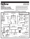
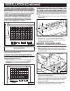
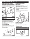
Model IA-29 Only
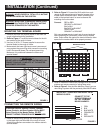
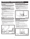
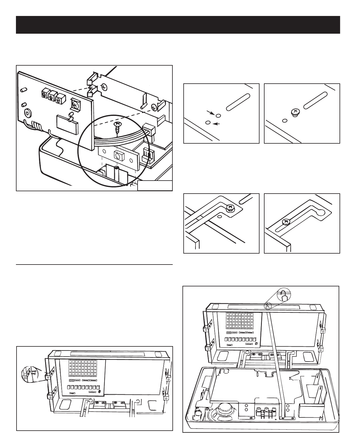
1. Refer to Figure 8. Locate the chime selector switch
mounting bracket in the master unit.
2. Remove and set aside the chime selector switch retaining
screw located in the master unit.
3. Remove and discard the square foam pads on the chime
selector switch PC board connected to the chime module.
4. Slide the PC board into the mounting bracket on the
master station.
5. Fasten the chime selector switch PC board with the
retaining screw (earlier removed).
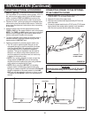
MOUNTING THE MASTER STATION
NOTE: If an optional IA-440 expansion module is to be
installed into the IM-4406 master station, it should be
installed before mounting the master station. Refer the
installation instruction provided with the expansion module
before performing the following mounting steps.
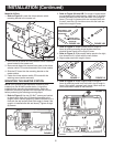
1. Refer to Figure 9. Use two (2) #6x
3
⁄8˝ screws per bracket
to attach each of the four (4) mounting brackets to the
rough-in frame. Before tightening, slide the bracket so it is
flush with the wall surface (flush with rough-in frame if the
rough-in is installed after the wall board). Tighten all eight
(8) screws.
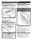
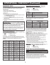
2. Refer to Figure 10A and 10B. For rough-in frames which
are recessed into the wall opening, insert two (2) shoulder
screws (provided) into the front two holes in the rough-in
frame. For rough-in frames which are mounted flush with
the wall, insert two (2) shoulder screws into the back two
holes in the rough-in frame.
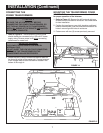
3. Refer to Figure 11. Attach master panel to rough-in
frame by placing mounting hinge keyhole slots over
shoulder screw heads in the rough-in frame.
4. Refer to Figure 12. Slide master station panel to the right,
then forward until it is flush with the wall surface.
5. Align master panel with rough-in frame.
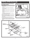
6. Refer to Figure 13. Attach support strap to rough-in
frame by attaching metal hook into hole in top of rough-in
frame. Using pliers, squeeze hook closed. Hook must not
come loose when master is later secured.
6
INSTALLATION (Continued)
FIGURE 8
FIGURE 10A FIGURE 10B
FIGURE 11 FIGURE 12
FIGURE 13
BACK HOLE – FOR
FLUSH MOUNTED
ROUGH-INS
FRONT HOLE –
FOR RECESSED
ROUGH-IN
FIGURE 9