


3
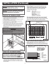
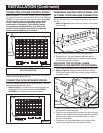
CONTENTS OF CARTON
Check (✓) for the following IM-4406 carton contents.
❏ IM-4406 master station
❏ Terminal board
❏ Transformer cover
❏ Hardware bag assembly containing:
2 - shoulder screws
12 - No. 6 x 3/8 screws
4 - colored panel mounting screws
4 - ‘L’ panel mounting brackets
❏ Homeowner’s manual with room labels
❏ Installation instructions
❏ Product Registration Warranty Card
NOTE TO INSTALLER: Do not discard these
installation instructions. Please transfer all
installation instructions, warranty registration
and homeowner’s manual to the homeowner.
PRECAUTIONS AND GUIDELINES
The NuTone IM-4406 master station has been designed for
ease of installation. Please read and follow ALL installation
instructions, guidelines and precautions. Any deviation from
these instructions or miswiring combinations may result in
unit failure and void of warranty.
WARNING!
120 Volt AC Power to Transformers in the IR-105
Rough-in MUST Remain OFF until ALL System Wiring
at the Master and Remote Stations is Complete.
• Observe all local building regulatory codes in your area.
•All screw terminals at the master and remote stations must
be secure.
• Observe all color code connections of wires when
connecting the remote stations to the master.
• The IM-4406 is designed to be installed with only NuTone
specified wire. No other wire should be used. The use of
wire other than NuTone wire will void all NuTone warranties
and may result in faulty installation and improper operation.
Use NuTone IW-2, 22 ga. twisted pair for connecting:
• Door speakers to master
• Remote controls to speakers
• Speaker volume control (IC901) to master
• Speaker volume control (IC901) to speakers
•Electronic chime audio output to master
• Pushbutton to chime module
Use NuTone S-143, 18 ga. twisted pair for connecting:
• Pushbutton to electronic chime
•Electronic chime to chime transformer
Use Nº14/2 power cable with ground, Class 1 UL Listed
(Observe local codes) for connecting:
•Transformers to 120v AC
Use shielded audio cable for connecting external audio
sources to the master station.
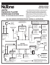
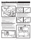
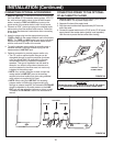
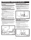
REMOTE STATION WIRING
An individual 6-wire cable (IW-6) must be connected from
each remote station or remote control location to the master
station’s terminal board.
Maximum station wire length: 750 ft.
Maximum total length of IW-6 cable per system: 4,000 ft.
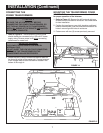
MAXIMUM NUMBER OF REMOTE STATIONS
The master station will accommodate up to 9 connections
at the terminal board. These connections can be any
combination of remote stations, remote controls or volume
controls. It will also accommodate 3 door speaker
connections.
If more than 9 stations are required, use the optional
Model Nº IA-440 expansion kit. This will allow an additional
6 connections at the master.
IMPORTANT!
NuTone cannot be responsible for
improper system operation that results from
interference generated by light dimmers, fluorescent
lighting fixtures, and similar electrical products. Such
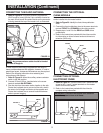
interference must be corrected at the source. TO HELP
REDUCE THIS INTERFERENCE, ALL WIRING
CONNECTIONS TO THE MASTER MUST BE PLACED
AT LEAST 12 INCHES FROM ANY AC POWER WIRING.
AVOID RUNNING INTERCOM WIRES PARALLEL TO
AC POWER WIRING.
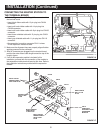
INSTALLATION
NOTE: NEVER connect more than one remote
station to a set of screw terminals.
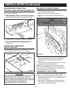
IMPORTANT WARNING!
THE POWER TRANSFORMER CONTAINS AN
INTERNAL FUSE.
DO NOT SHORT THE LOW VOLTAGE CONNECTING
SCREWS OF THE TRANSFORMER OR THE
TRANSFORMER WILL BE DESTROYED!
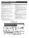
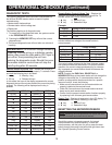
WIRING SPECIFICATIONS
See the IR-105 master rough-in frame installation instructions
for detailed wiring information.
Use NuTone IW-6, 3 twisted pair for connecting:
• Remote controls to master
• Remote stations to master