


Installing the
Wall-Mount Volume
Control in your Wall
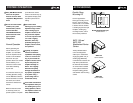
Carefully feed the Speaker
Cable back into the wall
and secure the Wall-Mount
Volume Control to the
bracket using the supplied
screws. Then install the
Decora® faceplate using the
supplied faceplate screws.
(See Figure 9)
Mounting the
In-Ceiling Speakers
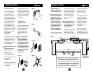
Remove the grille from the
In-Ceiling Speaker by bend-
ing the last quarter inch of
a small paper clip into an
“L” shape and inserting it
into one of the holes at the
edge of the grille. Figure 8
illustrates how to connect
the Speaker Cable to the
In-Ceiling Speakers.
Be sure to observe proper
polarity when connecting
the Speaker Cable to the
In-Ceiling Speakers.
Connect the wires:
Red = Right Positive (+)
Black = Right Negative (-)
White = Left Positive (+)
Green = Left Negative (-)
Once the Speaker Cable is
connected to the In-Ceiling
Speaker, conceal the excess
wire inside the ceiling cavity.
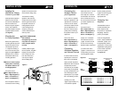
To install the in-Ceiling
Speakers, first rotate the
clamps inward so that they
sit flush against the side of
the speaker. Insert the In-
Ceiling Speaker into the
cutout and tighten the
clamps by turning the
screws clockwise with a
drill or by hand.
DO NOT OVERTIGHTEN
THE SCREWS.
Overtightening the screws
may break the clamps or
make the grille difficult
to install.
Carefully install the grille
into the speaker. The grilles
fit tightly to prevent them
from coming loose over
time. Some effort and
care may be required
when installing them.
Figure 9
7
INSTALLATION
!
!
!
8
Connecting the
Speaker Cable to
your Equipment
If your receiver or amplifier
has both “Speakers A” and
“Speakers B” connections
on the rear of the chassis,
connect the Cable connect-
ed to the Speakers to “A”.
Be sure to observe proper
polarity when connecting
the Speaker Cable to your
equipment.
Connect the wires:
Red = Right Positive (+)
Black = Right Negative (-)
White = Left Positive (+)
Green = Left Negative (-)
Connecting
Additional Speakers
and Volume Controls
In order to listen to several
speaker pairs at the same
time, each run of Speaker
Cable (and their respective
Wall-Mount Volume Controls
and Speakers) must be
connected to your amplifier.
This is easily accomplished
by using standard wire nuts
and connecting the other
speaker pairs to your ampli-
fier in the following manner:
a) Simply cut a short
“pigtail” (approximately 12”)
of 4-conductor Speaker
Cable and remove 2” of the
outer sheath from both
ends. Strip 3/8” of the col-
ored insulation from each of
the four conductors at one
end, and connect this end to
your stereo amplifier’s out-
put terminals.
Connect the wires
Red = Right Positive (+)
Black = Right Negative (-)
White = Left Positive (+)
Green = Left Negative (-)
b) Strip 3/4" of insulation
from both the end of the
“pigtail” and from the end
of each of the incoming
Speaker Cable’s conductors.
c) Connect each of the
“pigtail’s” conductors to its
corresponding color on the
incoming Speaker Cable
feeds by twisting the wires
together and securing them
with a wire nut of the
appropriate size.
Protecting Your
Amplifier
The Wall-Mount Volume
Controls included in the
Music Anywhere! Kits
incorporate an “Impedance
Magnifying” feature to
protect your amplifier.
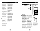
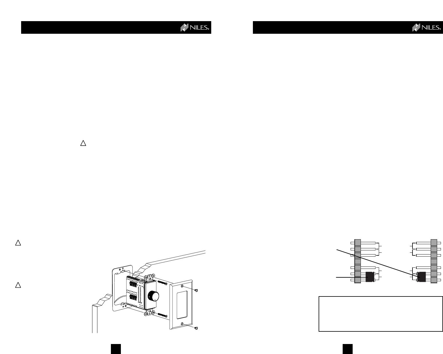
To set the “Magnification
Factor”, simply straddle the
small black “jumper” over
the appropriately marked
“jumper pins” for the correct
magnification setting based
on the number of speaker
pairs in your system.
(see Figure 10)
ADDING ON
SETTING THE MAGNIFICATION FACTOR
1 – 2 speakers pairs set jumper on ..................... 2X
3 – 4 speakers pairs set jumper on ..................... 4X
5 – 8 speakers pairs set jumper on ..................... 8X
9 – 16 speakers pairs set jumper on ................... 16X
16 x
MAGNIFICATION
FACTOR
JP1 (LEFT) (RIGHT) JP2
MAGNIFICATION
FACTOR
8x
4x
2x
16 x
8x
4x
2x
Left
Jumper
Right
Jumper
Figure 10