


5 6
!
!
!
INSTALLATION
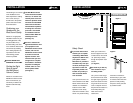
Cutting the Hole
Once you have decided
upon an ideal installation
location for the Wall-
Mounted Volume Control,
hold the Mounting Bracket
up to the wall surface. Level
the Mounting Bracket and
mark the wall by tracing the
inside perimeter of the
Mounting Bracket with a
pencil. Repeat the same
procedure for the In-Ceiling
Speakers using the supplied
template to trace a 9-1/4”
diameter hole for each In-
Ceiling Speaker.
(See Figure 3)
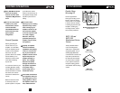
If you are cutting a painted
or wallpapered ceiling, use
a razor-knife to cleanly cut
the wallpaper. Then use a
drywall saw to cut the dry-
wall. (See Figure 4)
Be very careful not to saw
through existing wires,
pipes or structure.
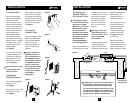
Installing the
Mounting Bracket
Place the Mounting Bracket
against the hole.
(See Figure 5)
Bend the tabs at a 90° angle
and insert into the hole.
(See Figure 6)
When the bracket is secure,
bend the tabs back against
the inside of the drywall and
insert the screws so that they
penetrate the tabs, clamping
the bracket to the drywall.
(See Figure 7)
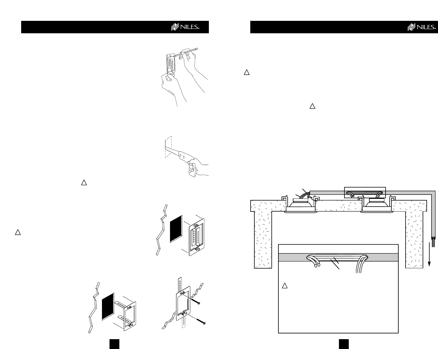
Running the
Speaker Cable
Conceal the Speaker Cable
between the stereo equip-
ment and the Wall-Mount
Volume Control, and
between the Wall-Mount
Volume Control and the
Speakers.
Be sure to measure the
approximate distance
from your equipment to
the Wall-Mount Volume
Control location, and from
the Wall-Mount Volume
Control to the first and
second Speaker locations
to ensure that you have
enough wire to complete
the installation.
(See Figure 8)
Figure 3
Figure 4
INSTALLATION
!
!
Connecting the
Speaker Cable to
the Volume Control
Connecting the Volume
Control backwards could
damage your amplifier.
Make sure to connect the
Speaker Cable coming
from your amplifier to
the INPUT of the Volume
Control (labeled AMPLIFI-
ER), and the OUTPUT of
the Volume Control
(labeled SPEAKERS) to
the In-Ceiling Speakers.
Strip the wire jacket back 2"
to expose the four colored
conductors and remove 1/4"
of insulation from the end of
each conductor. Twist the
end of each conductor so
the ends are not frayed.
Make sure that no more
than 1/4" of bare wire is
exposed.
Exposing too much wire
could cause the wires to
touch and create a “short”
which could damage
your equipment.
Connect the exposed ends
of each of the Speaker
Cable’s conductors to the
removable connectors pack-
aged with the Wall-Mount
Volume Control. (See
“Connect the wires” at
the bottom of page 7.)
If you are going to connect
more than two pairs of
speakers to the amplifier,
the Volume Control’s
“Impedance Magnifying”
jumpers must be reset.
(See Figure 10, Page 8
of this manual)
Refer to the Installation
section on page 8 of the
VCS-2D-IM Volume Control
manual included with your
Music Anywhere! In-Ceiling
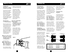
Figure 8
red and black
(unused)
to “speaker”
connection on
volume control
Carefully make a 12" incision in the wire jacket to
expose all four colored conductors (be careful
not to damage the colored conductors inside!).
Cut only the red and black wires at the top of the
incision and strip approx. 3/8" of insulation from
the ends of each conductor. Connect the red and
black wires to the speaker as shown above.
green
Right Speaker
Left Speaker
white
green
red black
red black
see Inset
Inset
Figure 5
white
Figure 7
!
Figure 6