


N
O
R
M
A
L
L
Y
O
P
E
N
C
O
M
M
O
N
N
O
R
M
A
L
L
Y
C
L
O
S
E
D
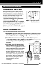
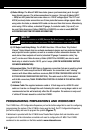
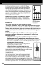
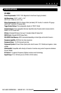
Figure 12.
Relay removable
connection plug
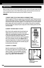
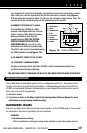
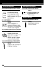
Figure 11.
RCA Jack Status
Connection
16
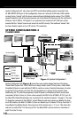
the TV signal and Status connection to the HT-MSU (Figure
11).If the source to be “synched” doesn’t have a video output,
one of the Niles Synching Accessories can be used instead of
video. Most Niles Synching Accessories use a 3.5mm jack as the
output. This 3.5mm jack must be changed to mate with the RCA
connector on the HT-MSU; use a Radio Shack 274-897 OR 274-
330 mini-plug to male RCA adapter.
IMPORTANT NOTE: RCA SOURCE STATUS INPUTS ARE DESIGNED
WITH HIGH-INPUT IMPEDANCES IN ORDER TO PRESERVE THE
QUALITY OF THE VIDEO SIGNAL WHEN USING A RCA Y-ADAPTOR.
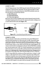
6) CONNECT 12V
The 12V trigger output jacks use 3.5mm mono plug with standard
“Tip and Collar” configuration. The tip is 12V DC 150mA when activated and the collar is
ground. Niles has two accessory cables for use with these 12V output jacks (FG00724 or
FG00933). Simply plug one of these cables with a 3.5mm mono plug into one of the three
assignable jacks. Plug the other end of the cable into the device that will be triggered or
activated.
The Niles QuickConfig
PC Configuration Software is used to assign (program) the
functionality of these jacks. The configuration software allows the 12V output to be
programmed as follows:
a) Output #1 can be configured to output 12V constantly or momentarily. A
momentary output would be used to activate a device that requires a pulse of
12V instead of a constant 12V. The pulse can be programmed for 1, 3 or 5 seconds,
then off when activated. The constant mode will output 12V continuously when
activated, and no 12V when deactivated.
b) Output #2 can be programmed just like Output #1, but
completely independent of output #1.
c) Output #3 configured for constant output only when
activated, but is also completely independent of outputs 1 and 2.
Please refer to the Niles QuickConfig Configuration manual for more
information about the 12V output programmability.
7) CONNECT RELAYS
The “Dry Contact Closure” relays use 2-conductor wire to pair
either the NO “Normally Open” or NC “Normally Closed” side of
the removable connector plug with the “Common”. NO or NC is
determined by which device you are triggering. Strip 1/4 inch of the
insulation from the end of each wire, and tightly twist the end of each
wire until no frayed ends remain. Use a small flathead screwdriver or