


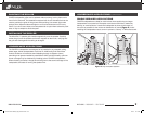


Figure 3. Securing the speaker wire with
a wire tie.
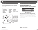
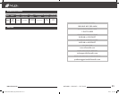
Figure 5. Inserting the loudspeaker into
the opening hole.
Mounting clamps
require 1” clearance
to the sides of the
hole opening
NILES AUDIO – 1-800-BUY-HIFI – 1-760-710-0992
7
WWW.NILESAUDIO.COM
INSTALLING ThE LOUdSPEAKERS continueD
7. The speaker has black and red
spring-loaded connectors attached
to the Rear Wave Control enclosure
(Figure 3). Black is for the negative
(–) wire and red for the positive (+).
It is important to observe correct
wiring polarity. If you have wire other
than black and red, make sure you
connect it the same on the amplifier
end as the speaker end. Failure
to do so will adversely affect the
loudspeakers’ performance. Supports
are provided to secure the speaker
wire with wire ties. (not included)
8. A safety wire anchor is provided on
the Rear Wave Control enclosure
should you be required to secure the
loudspeaker assembly to a roof beam
or rafter (Figure 4).
9. Once the speaker wires and safety
wire are connected, raise the
mounting clips to a vertical position
as shown in Figure 5 and carefully
slide the loudspeaker with
attached Rear Wave Control
enclosure into the opening
hole (Figure 5). CM4PR
loudspeakers feature spring
loaded mounting clamps that
allow the speaker to remain flush
with the ceiling To remove a
CM4PR from the ceiling, simply
grasp the bezel edge and pull
on the speaker slowly. This will
cause the mounting clamps
to disengage and free the
loudspeaker.
NOTE: DO NOT CARRY THE SPEAKER
BY THE TWEETER OR TWEETER POST.
THIS MAY DAMAGE THE SPEAKER.
Figure 4. Attaching a safety wire.
INSTALLING ThE LOUdSPEAKERS
It is often easier to lay the speakers out on the oor and then transfer the locations
to the ceiling with a laser plumb bob. If you are using new construction brackets,
place string across the centers of the bracket to provide a way to align the bracket
to the laser. Remember, you will need 1” to the sides of the mounting hole for the
mounting clamps to secure the speaker to the drywall and you will need at least 5”
of clearance to one side within the opening for the CM4PR’s Rear Wave Enclosure.
1. Once you have determined a possible position for the hole cutout, drill a
1/8” pilot hole just barely through the ceiling (1/2” to 5/8” deep in most
homes) in the center of your proposed loudspeaker location.
BE VERY
CAREFUL NOT TO DRILL THROUGH EXISTING WIRES, PIPES, OR STRUCTURE.
IF YOU FEEL ANY EXTRA RESISTANCE AS YOU ARE DRILLING, STOP.
2. Cut a foot-long piece of coat hanger. Bend the wire (creating a right angle)
leaving 3-5/16” at one end (this allows for the extra width of the Rear Wave
Enclosure). Poke the “L-shaped” wire into the pilot hole and turn it in a
complete circle and move it into the ceiling cavity to make sure you have
approximately 3-5/16” of depth within the ceiling. If the wire’s movement is
obstructed by anything, fill the hole(s) with spackle and try another location
(If there is any risk of uninsulated electrical connections within the ceiling
area, use insulating gloves or other materials or consult with an installation
professional before proceeding).
3. If the coat hanger moves freely in a complete circle and you have sufficient
depth, tape the template to the ceiling and proceed to layout the other
speakers. Once you are comfortable with all speaker locations, use a pencil
to lightly outline the circular template.
4. Drill the starting point of your cut with a 1/4” bit.
5. If you are cutting drywall, use a sheetrock or keyhole saw. Cut the hole with
the saw at a 45° angle. That way the drywall section can be replaced cleanly
if there is an unseen obstruction behind the wall.
IMPORTANT: BE VERY
CAREFUL NOT TO SAW THROUGH EXISTING WIRES, PIPES, OR STRUCTURE. IF
YOU FEEL EXTRA RESISTANCE AS YOU ARE CUTTING, STOP.
NOTE: DO NOT INSTALL LOUDSPEAKERS BEFORE THE DRYWALL HAS BEEN COMPLETELY
FINISHED AND PAINTED.
6. Prep the speaker wire by stripping 1/4”-1/2” from each speaker lead. Twist
the strands or tin the leads with solder to ensure there are no stray strands
that could short and possibly harm the amplifier.
(CONTINUED ON NEXT PAGE)
9901197-RevA-CM4PR_Spk_Manual-V4.indd 6-7 8/17/11 10:11 PM