


6
REAR PANEL
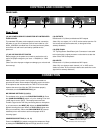
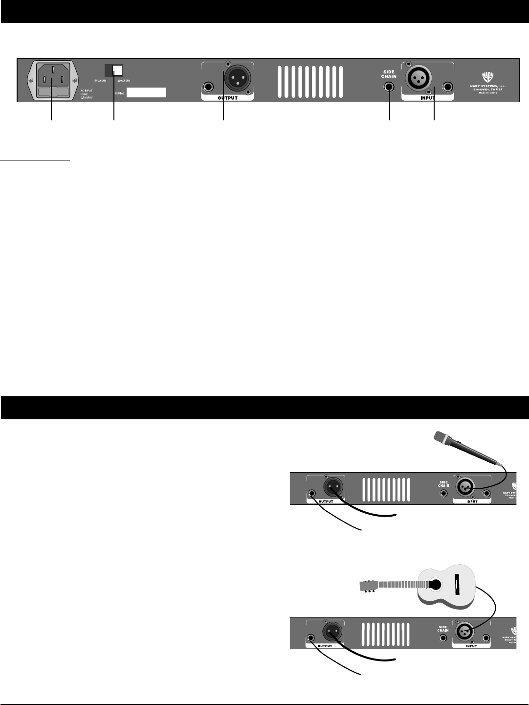
Rear Panel
(16) AC POWER CORD IEC CONNECTOR WITH INTEGRATED
FUSE HOLDER
This standard IEC power cord receptacle is used to connect the
AC power to your unit. It features a built-in fuse holder for a 5 X
20mm, 0.5A/250V slow-blow fuse. If the fuse continuously blows,
shut off the unit and have it serviced by qualified service
personnel.
(17) AC VOLTAGE SELECT SWITCH
Before plugging in the power cord, check to see that the unit is
set for the proper voltage for your area: ~115V(60Hz) or ~230V
(50Hz).
(Note: Use at the improper voltage can damage your unit and void
the warranty.)
(18) OUTPUTS
Unbalanced 1/4" (6.3mm) and balanced XLR outputs
(Note: Only one output (1/4" or XLR) can be used at one time. Do
not connect to both at the same time, or the signal will be
severely distorted.)
(19) SIDE CHAIN
1/4” Tip-Ring-Sleeve Send/Return jack. Connect an insert cable
to this jack and to a signal processor or other device to alter the
action of the TMP-3 compressor.
(20) INPUTS
Unbalanced 1/4" (6.3mm) and balanced XLR inputs.
(Note: Only one input per each channel (1/4" or XLR) can be
used at one time. Do not connect to both at the same time or the
signal will be severely distorted.)
CONTROLS AND CONNECTORS
(16) (17) (18) (19) (20)
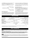
CONNECTION
Make sure the TMP-3 power cord is properly connected to a
grounded AC outlet. Note examples illustrating proper connection
of microphones and instruments to the TMP-3. Do not use both
inputs at the same time. After the TMP-3 has been properly
connected, turn the POWER SWITCH (1) on.
MIC PREAMP SETTINGS (2,3,4,5,6)
For condenser mics, press in the PHANTOM POWER (4). Press
the +30dB GAIN/NORM (2) switch in if you’re sending a line level
(+4dB) signal into the TMP-3. This helps prevent overload.
Provide a signal to the TMP-3 by connecting either a microphone
or an instrument to the INPUT (20). Adjust the GAIN CONTROL
(5) while sending the signal. When the CLIP LED (6) lights more
than just occasionally, reduce the GAIN CONTROL (5) (counter-
clockwise) one or two marks to achieve the proper level of
incoming signal.
COMPRESSOR SETTING (11, 12, 13)
Press in the IN/OUT (11) switch to engage the compressor. Begin
by setting the THRESHOLD (13) control high (around 3 o’clock)
+4dB Line Level Output. Do not
connect to a Mic Input.
Connect to mixer line-level input.
+4dB Line Level Output. Do not
connect to a Mic Input.
Connect to mixer line-level input.