


CONTROLS AND CONNECTORS
5
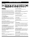
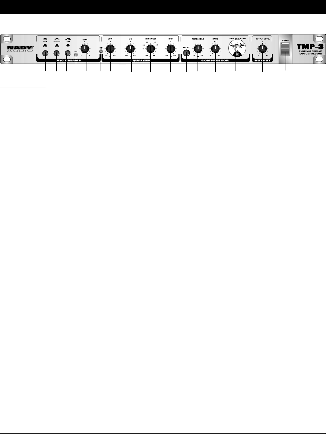
FRONT PANEL
Front Panel
(1) POWER SWITCH
Use this switch to power unit ON or OFF. The integrated LED will
light when the unit is ON. Before turning on this unit, verify
connection to the proper voltage AC source, check all connections
and turn down the level controls of equipment connected to the
outputs.
(Note: The TMP-3 will not output audio for approximately
16 seconds after power up due to the time it takes for the tubes to
warm up. Do not turn up the audio until after this warm up period
to avoid possibly damaging speakers or your hearing due to
improper level settings.)
(2) +30dB GAIN/NORM SWITCH
Use the +30dB GAIN/NORM switch to set the gain range of the
INPUT CONTROL (2). When the switch is out, the TMP-3
operates in Normal mode, depressing the switch adds +30dB of
gain. Push the switch in for microphone applications when more
level is needed.
(3) PHASE REVERSE / NORM SWITCH
When the switch is in the Out position the output signal is normal.
Depressing the switch reverses the phase of the output signal. In
multi-microphone applications, mic placement can affect the
phase of the signals. If your sound is “thin” or “not quite right”,
reverse the phase to correct the problem.
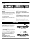
(4) PHANTOM POWER SWITCH
Use the PHANTOM POWER to supply power to all microphones
requiring +48V phantom power. The TMP-3 phantom power is
engaged and disengaged with this switch Phantom power is
applied to pins 2 and 3 of the XLR INPUT (20) jacks when this
switch is pushed in. To disengage phantom power, set the switch
in the out position. PHANTOM POWER LED (4a) lights when
PHANTOM POWER is engaged.
(5) GAIN CONTROL
Controls the amount of gain in the tube mic preamp circuit. This
control adds from 0dB to +10dB of gain.
(6) CLIP LED
When lit, this LED indicates clipping or possible distortion in the
mic preamp circuits. Reduce the GAIN CONTROL (5) so that this
LED only lights occasionally.
(1)(9)(8)(7)(6)(5)(4)(3)(2) (10) (11) (12) (13) (14) (15)
(7) LOW LEVEL EQ CONTROL
Adjusts level of low frequencies, from 20Hz to 150Hz.
(8) MID LEVEL EQ CONTROL
Adjusts level of mid frequencies, as selected by the MID SWEEP
(9) control. This sweepable filter has a Q or width of 1.
(9) MID SWEEP CONTROL
Selects the frequency to be boost/cut by the MID LEVEL (8)
control. Adjustable from 300Hz to 5KHz.
(10) HIGH LEVEL EQ CONTROL
Adjusts the level of high frequencies, from 10kHz to 20kHz.
(11) IN/OUT SWITCH
Switch for engaging the compressor circuits. The compressor is
active when the switch is in.
(12) THRESHOLD CONTROL
Sets the point that the input signal must reach for compression to
begin.
(13) RATIO CONTROL
This control sets the signal to compression ratio. This ratio relates
to the amount of increase of input compared to output signal.
Thus, for example, at a 1:1 ratio, a 1dB increase of input signal
will result in a 1dB increase of out signal. At 2:1, a 2dB increase of
input signal will result in only 1dB increase of output signal. At 8:1,
an 8dB increase of input signal will result in a 1dB increase of
output signal.
(14) OUTPUT LEVEL VU METER
The output level of the TMP-3 can be monitored using the analog
OUTPUT LEVEL VU METER. The meter’s 0dB marking repre-
sents +12dB at the XLR output and +6dBu at the 1/4" output. The
output meter will also reflect any attenuation due to the output
limiter when it is engaged.
(15) OUTPUT CONTROL
The OUTPUT CONTROL sets the output level of the TMP-3.
When the control is fully counterclockwise, the output level of the
TMP-3 is zero. Turning the control clockwise increases the level of
the output to a maximum of +10dB of gain. This gain is in addition
to the existing input gain.
(4a)