


8
Nady Systems Inc. – PSS-300 Portable Sound System
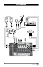
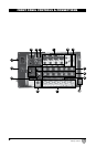
FRONT PANEL CONTROLS & CONNECTIONS
1. CHANNEL 1-4 XLR / ¼” INPUT - The XLR mic inputs are an electronically balanced XLR type
designed to accept mic level signals from any balanced or unbalanced low impedance (Low Z)
microphone. The XLR jacks are configured for: Pin1 = ground, Pin2 = positive (+), Pin3 = negative
(-). The 1/4” mono line inputs are designed to accept unbalanced line level signals such as those
from keyboards, drum machines, or samplers.
2. CHANNEL 5/6 STEREO ¼” / RCA INPUTS - The TS ¼” or stereo RCA line level inputs can be
used for connecting CD players, Tape Decks, and other audio equipment with line level outputs.
3. CHANNEL 7/8 STEREO RCA INPUTS - The stereo RCA line level inputs can be used for connect
ing CD players, Tape Decks,and other audio equipment with line level outputs.
4. REVERB SWITCH - The REVERB switch can be used to add an effect to the mic or line input on
any of the inputs 1-4. Once engaged, the green LED next to each REVERB switch will illuminate,
indicating the REVERB is ON.
5. TREBLE CONTROL - Turn to the right to boost high frequencies, adding crispness too percussion
from drum machines, cymbals and synths. Turn to the left to cut these frequencies, reducing sibi
lance or hiss. The control has a shelving response giving +/-10dB of boost or cut at 10kHz.
6. BASS CONTROL - The bass control shelving response gives 10dB of boost or cut at 100Hz. Add
warmth to vocals or extra punch to guitars, drums and synths by turning to the right. Turn to the left
to reduce stage rumble, hum or to improve a mushy sound.
7. CHANNEL FADER - The channel faders determine the output signal level to the Master Mix bus.
They offer a smooth logarithmic taper more often associated with much more expensive console
for optimum control of the signal.
8. MASTER FADER - The master fader determines the output signal level of the Master Mix bus.
They offer a smooth logarithmic taper more often associated with much more expensive console
for optimum control of the signal.
9. REVERB CONTROL KNOB - The REVERB control knob is used to adjust the amount of reverb
added to all channels that have the REVERB switch engaged.
10. MONITOR VOLUME KNOB - The monitor volume knob controls the output level of the line and
stereo RCA record out. Note that the monitor out (11) is intended to be used with powered speak
ers or other devices that require no additional (wattage) power.
11. MONITOR OUT - There are 2 ¼” TS connectors that can be used to connect to powered speakers
or any device not requiring additional (wattage) power.
12. REC OUT - The REC OUT stereo RCA outputs can be used to connect to an external recording
device and is controlled by the (7) individual channel faders. Note that it is important to monitor
and set the input of your recording device prior to recording to ensure no clipping of the signal
during the process.
13. SPEAKER OUT - The PSS-300 has two ¼” TS connectors, which are powered outputs used to
connect your left and right speakers. Use the included speaker cables to connect the speakers
CAUTION: The total impediance load for each side of the amplifier must not be less than 6 Ohms.
Do not connect additional speakers to the PSS-300 unless using (9) monitor out section (please
read above for more details).
14. POWER / PEAK INDICATOR - The POWER LED will illuminate Green when the main power switch
is turned on, and the red light will indicate the amplifier is near the clipping point. If the Peak
indicator is consistently light up, turn down the MASTER volume or the individual channel faders
until the indicator light does not flash consistently.
15. POWER SWITCH - Use the power switch to turn the PSS-300 on or off.
16. SPEECH / MUSIC SWITCH - The SPEECH/MUSIC switch is used to change the overall tone and
frequency response of the PSS-300. If the PSS-300 is used for a music application, engage the
switch for music-optimized settings, and disengage the switch for speech-optimized applications.
17. IEC INLET - Connect the supplied heavy gauge 3-pin IEC power cable here.
18. MIXER LOCKS - To release the mixer from the speaker, turn the mixer locks counter-clockwise
When transporting the PSS-300, make sure the mixer locks are tightly secured.