5
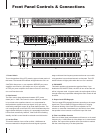
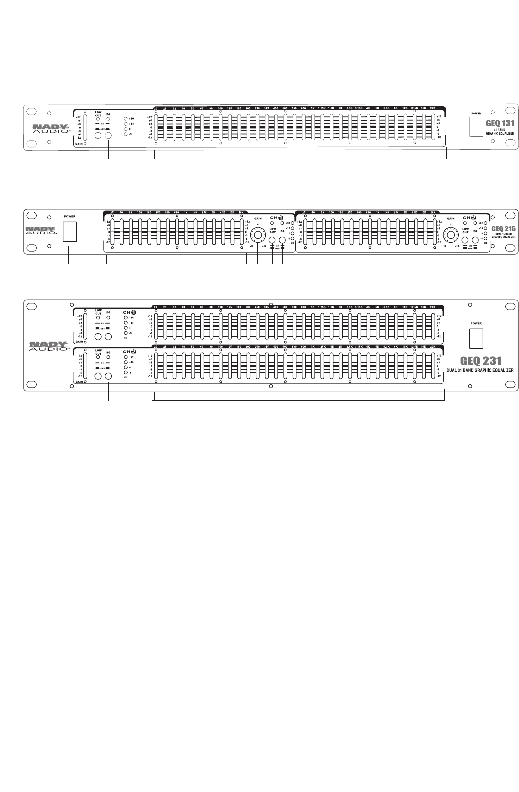
1. Power Switch
To turn the equalizer ON or OFF, press the upper or lower portion of
this button. The internal LED indicator will light when the unit is on.
CAUTION: Always turn on your equalizer BEFORE your power
amplifiers are turned on, and always turn off your equalizer
AFTER your power amplifiers have been turned off to avoid any
turn on/off transient noise.
2. Gain Control
The Gain control allows adjustment between OFF (center
detent) and +/-12dB. This control is used to adjust for variation
in input level to the equalizer channel, or to compensate for
the equalization applied to the input signal. Unity gain can be
achieved by setting this control to its center detent position. The
unit is equipped with a red Peak LED, which illuminates when the
signal reaches 3dB prior to clipping. It is acceptable for the Peak
LED to flash occasionally, however, if the Peak LED is flashing
steadily, the Gain control should be reduced to avoid distortion.
3. Low-Cut Filter
This switch enables a low cut filter at 40Hz, 12dB/octave to
remove unwanted low frequencies from the signal to prevent
stage rumble and low frequency resonance that can occur while
using speakers in an enclosed acoustic environment. The LED
status indicator will light yellow when the Low Cut is enabled.
4. EQ ON/OFF
This switch enables or bypasses the equalizer filters. If you
disable the EQ ON/OFF switch, the LED will turn off and the unit
will be in bypass mode. In bypass mode, the audio signal will flow
through without any equalization although the Gain control will still
be active.
5. Output Level LED Bargraph
This four-stage LED bargraph illuminates according to the output
signal level. The red Peak LED lights at 3dB prior to clipping.
Occasional blinking of the Peak LED is acceptable, but if it
remains on more than intermittently you should turn down either
the equalizer’s level controls or reduce the input Gain level.
6. Filter Level Slider Controls
Each one of these linear potentiometers will boost or cut its noted
frequency by +/-12dB. When all of the sliders are in center detent
position, the output of the equalizer is flat. Each slider is marked
with the center frequency of its band pass filter.
Front Panel Controls & Connections
2 3 4 5 6 1
2 3 4 561
2 3 4 5 6 1


