FRONT PANEL CONTROLS (FIGURE 2)
1. POWER ON/OFF
Press this button to switch the amplifier on or off. The Power
On/Standby (No. 2) indicator located just above the power button and
Protection indicator will light up. After a few seconds, the Protection
LED will turn off, indicating that the amplifier is ready for use.
The C270 can also be remotely switched from On to Stand-by and
vice-versa using the 12V trigger input on the back panel. For the
12V trigger input to work, the C270 must first be turned on by
means of the Power switch, and the switch must be left in this
position. Using the 12V trigger source component, switch its
12Vtrigger output to on and off. The C270’s Trigger Input will now
follow the source component’s 12V trigger output. Ensure that the
Auto Trigger switch on the back panel is in the AUTO position and
that the 12V trigger input is connected properly. Refer to section
“12V Trigger In” in the chapter above for more information.
NOTE: In Stand-by mode the C270 uses very little power.
However, it is recommended that you switch the unit totally off if
it is not going to be used for more than a couple of days. Switch
off completely by pressing the POWER button on the front panel
(No. 1), all lights will extinguish.
2. STAND-BY/PROTECTION INDICATOR
Upon switching Power on, the indicator will light up red and after a
short pause turn to green to indicate the amplifier is ready for use.
In cases of serious abuse of the amplifier, such as overheating,
excessively low loudspeaker impedance, short circuit, etc. the
amplifier will engage its Protection circuitry. The indicator will
light up red and the sound will be muted. In such a case, turn the
amplifier off, wait for it to cool down and/or check the speaker
connections, making sure the overall loudspeaker impedance
doesn’t go below 4 ohms or 8 ohms in Bridge Mode. Once the
cause for the protection circuitry to engage has been removed,
switch the amplifier On again.
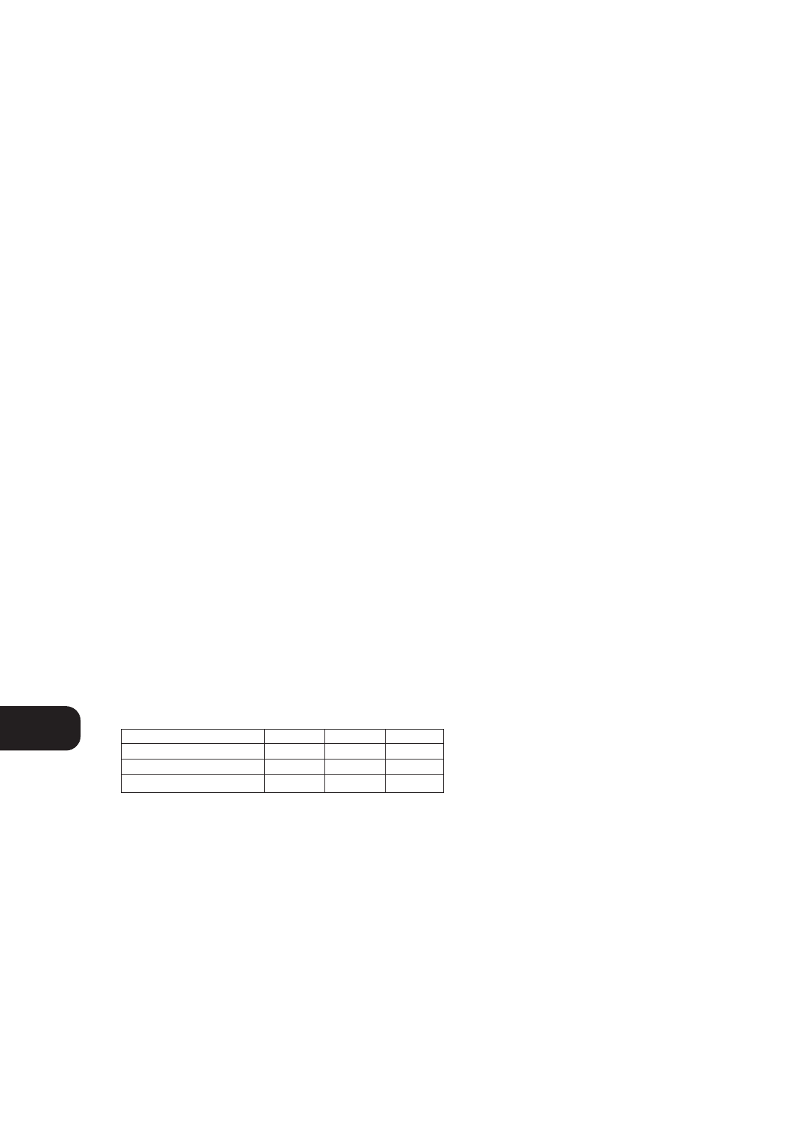
The diagram below shows the operation of the Stand-
by/protection indicator:
3. SOFT CLIPPING™ INDICATOR
The green SOFT CLIPPING™ indicator shows that the Soft
Clipping™ mode is engaged. Refer also to chapter “Rear Panel
Connections”, section 7; “Soft Clipping™” for more information.
4. BRIDGE MODE INDICATOR
The BRIDE MODE indicator lights up (amber) when the C270 is
switched to Bridge Mode. Refer also to chapter “Rear Panel
Connections”, section 6, “Bridge Mode” for more information.
GB
6
Green Amber Red
Normal Operation •
Stand-by •
Protection •


