


A3.2 Integrated Amplifier Instructions for use Page 6 of 9
Issue 1: March 2002
Various lengths are available in the Nu-
Vista interconnect range. Please contact
your local dealer for more information.
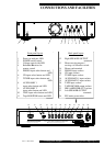
OUTPUT CONNECTIONS
Connect your loudspeakers to the terminals
on the back panel marked as LEFT and
RIGHT SPEAKER outputs.
PRE-AMPLIFIER OUTPUT
The A3.2 Integrated amplifier has its pre-
amplifier output available from RCA sock-
ets on the back panel marked PRE-OUT,
and is controlled by the volume adjustment.
This is to allow “bi-amplification” using
suitable external amplifiers and crossover
networks to power the speaker drive com-
ponents separately, giving noticeable
improvement in clarity, imaging and bass
weight.
In this arrangement, typically the A3.2’s
speaker outputs are used to drive the speak
-
er’s “tweeter” (high audio frequencies), and
an external stereo amplifier drives the
“woofer” (low frequencies).
The A3.2’s PRE OUT RCA sockets would
therefore be connected to the input of the
external “woofer” amplifier in this exam-
ple.
If you are in doubt about bi-amplification,
please contact your dealer for advice.
BEFORE SWITCHING ON
Plug the accessory IEC mains lead into the
rear panel socket, then the other end into a
wall outlet.
Turn the volume control on the front panel
to minimum (anticlockwise).
CONNECTIONS
All input, output and power connections
should be made with the mains power
switched OFF.
INPUT CONNECTIONS
The A3.2 Integrated amplifier has one pair
of phono inputs, which can be used either
for moving magnet (MM) or moving coil
(MC) pickups.
The phono input sensitivity requirement
can be changed from MM to MC by press-
ing the push-button switch located on the
rear panel.
Important - Do not operate the MM/MC
switch with the volume control turned up.
Some turntable/pickup arm combinations
are fitted with an extra wire for chassis
earthing. This should be connected to the
earth terminal on the back panel.
The A3.2 amplifier also has five “line
level” inputs which are electrically identi-
cal, and therefore suitable for use with any
source component having an output of at
least 300mV. The sockets on the rear
panel are marked CD, TUNER, AUXIL-
LIARY 1, AUXILLIARY 2, and TAPE,
to correspond with function buttons on the
front panel.
Connect the left and right outputs from
your CD player, tuner or phono/record
deck to the appropriate RCA input sockets
on the back panel.
Connect the A3.2’s TAPE input sockets to
the line output of your tape recorder, and
A3.2’s TAPE RECORD output sockets to
the line input sockets of the tape deck.
For the best results we recommend using
either Musical Fidelity X-LINX "no-non-
sense" cables for this connection or the
highly rated Nu-Vista leads with integral
RFI suppression. (continued)