


dmc1
www.mssystems.com | 800.421.1587 | www.mssystems.com
Page
6
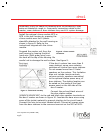
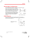
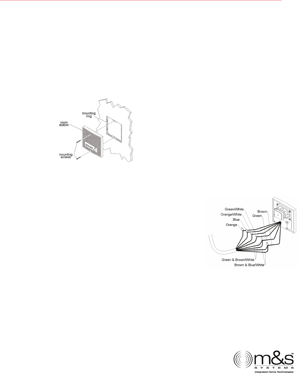
Connect each colored conductor to its respective screw terminal. The
screw terminals are marked with the appropriate wire colors. Note:
Some screw terminals have more than one wire connected to them.
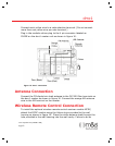
Mount each room station to its mounting ring using the two screws
provided with each dmc1 room station as shown in figure 2.
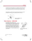
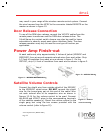
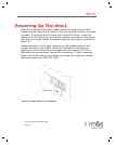
Patio Station – DMC1RW
At each patio station location, strip
approximately 4 inches of jacket from the CAT5
wire and separate the colored conductors. Strip
½ inch of insulation from each conductor and
connect each colored conductor together using
wiring wire nuts as shown in figure 3. Note:
Some wires are doubled up when connected to
the room station. Mount the patio station to the
housing using the 2 screws provided with the
room station.
Figure 3 – Patio station wiring
connections
Figure 2 – Attaching the room
station to the wall