


6
Mr. Heater | Gas-Fired Low-Intensity Infrared Heater Operating Instructions and Owner’s Manual
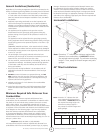
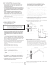
Where can the heater be installed?
The MHT tube heater is intended for installation in the following
areas:
• Residential applications, such as:
— garages
— greenhouses
— workshops
• Light industrial/commercial applications, such as:
— entranceways
— lobby areas
— Lunch rooms
— aircraft hangars (see Section 2 for restrictions)
— public garages ( see Section 2 for restrictions)
Where can’t the heater be installed?
The MHT tube heater is not intended for installation in the
following areas:
•Residential living or sleeping areas
•Basements
Installer’s responsibility
The MHT tube heater , as well as the gas and electrical supply,
and the venting of the heater must be installed in accordance with
applicable specications and codes. Only rms (or individuals) well
qualied in this type of work should install the system. Consult local
Building Inspectors, Fire Marshals for further guidance.
Use the information given in this manual together with the cited
codes and regulations to perform the installation. The installer must
furnish all needed materials that are not furnished as standard
equipment. It is also the installer’s responsibility to see that the
materials and installation methods used, result in a job that is
workmanlike in appearance and is in compliance with all applicable
codes and requirements to this manual. The installer must give this
manual to the owner.
Section 2 PLANNING
General
This section provides the following information:
•Denes the gas, electric and venting requirements for the
MHT tube heater.
•Species the national standards and applicable codes that
apply to the gas, electric and venting requirements.
•Species the national standards and applicable codes that
apply to non-residential installations.
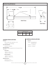
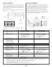
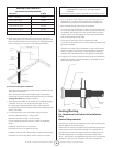
Gas Service Requirements:
System Requirements
Inlet Connection
Connection: ½” Male NPT
Inlet Pressure
Natural Gas:
Minimum - Inlet 5.0” w.c.
Maximum – Inlet 10.5” w.c.
LP Gas (propane):
Minimum – Inlet 10.5” w.c.
Maximum – Inlet 13.0” w.c.
Manifold Pressure
Natural Gas: 4.0” w.c.
LP Gas (propane): 10.0” w.c.
Type of Gas
The type of gas appearing on the nameplate must be the type
of gas used. Installation must comply with local codes and
recommendations of the local gas company. United States: Refer
to National Fuel Gas Code, ANSI Z223.1 – latest revision, (same as
NFPA Bulletin 54). Canada: Refer to Can 1-B149.1: Installation Codes
for Gas Burning Appliances.
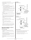
Gas Supply Lines
The size of the gas supply lines must comply with local codes and
recommendations of the local gas company. United States: Refer
to National Fuel Gas Code, ANSI Z223.1 – latest revision, (same as
NFPA Bulletin 54). Canada: Refer to CAN 1-B149.1: Installation Codes
for Gas Burning Appliances.
A 1/8” NPT plugged tap must be installed in the gas line connection
immediately upstream of the heater that is farthest from the gas
supply meter. The tap is required for checking system gas pressure.
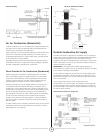
Meter and Service
Meter and service must be large enough to handle all the heaters
being installed plus any other connected load. The gas line which
feeds the system must be large enough to supply the required gas
with a maximum pressure drop of ½” w.c. When gas piping is not
included in the layout drawing, the local gas supplier will usually help
in planning the gas piping.