SS-150THX satellite speaker
page 8
important, preferably with the cabinet's bottom at least two feet above a seated listener's head. In fact, it is even better
if the speakers are located above standing listeners' heads, for when listeners are standing or walking around the room.
c. WALL LOCATION
The SS-150THX can be mounted on either the side walls or on the back wall, or even directly in a corner. They
can be flush on the wall, on shelves, on brackets, etc. The Tripole's great flexibility makes it very forgiving of room
placement that is less than optimum.
The Tripole will give you a combination of an enveloping sound with directionality. You will hear directional
effects, and even imaging when the recording has these qualities. Yet at the same time you will also hear a diffuse
sound from the Dipole drivers mounted on the left and right cabinet baffles.
If the sound lacks the directionality you desire, point the front baffles directly at the main listening position.
Omnimount brackets are very useful for this. If the sound is too directional, angle the speakers towards the back wall
or the side wall surface directly behind them. By reflecting sound behind the listening position, you may increase the
sense of envelopment in the sound.
d. USE OF MULTIPLE PAIRS OF SURROUNDS
Some listeners prefer multiple pairs of surround speakers. In very large rooms, this may even be necessary.
Multiple speakers can make a dramatic improvement and provide a broader and deeper surround effect. When using
multiple pairs of surround speakers, a symmetrical installation pattern works best. For example, one pair could be
mounted on the back wall of the room, mounted equidistant from the back corners, with the other pair mounted on the
side walls of the room, equidistant from the same back corners. When using two pairs of Tripoles, make sure that
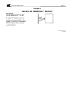
the speakers on the back wall have their arrows labelled "Point Arrow At Screen" pointed at the side walls of the room.
7. CUSTOM MODES & REMOTE OPERATION
IMPORTANT: The following options are provided for enthusiasts and installers
who wish to experiment with their systems.
The design of the SS-150THX provides a tremendous amount of flexibility. Because it is designed as if it is two
separate speakers (a Direct radiator and a Dipole), you can independently vary the amount of output from either the
Direct radiator or the Dipole elements.
By adjusting the ratio of sound produced by these elements, you can fine-tune the speaker to your listening
environment or personal preference. You make these adjustments by choosing which input terminals, jumpers, and
(if desired) resistors are used to connect the speaker to the amplifier.
PLEASE NOTE: The sensitivity of the speaker is slightly different in each of these modes. For critical listening,
when switching from one mode to another, you should re-calibrate the level of the surround channels.
Regardless of configuration, the Ground (-) lead from the amplifier must connect to Terminal 2.
a. THX Dipole Mode
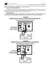
See page 6. To operate in the Dipole (THX) mode, connect the positive (+) lead to Terminal 1. Use no jumper.
b. Tripole Mode
See page 6. To operate in the Tripole mode, must connect the positive (+) lead to Terminal 1 and insert the
jumper between terminals 3 and 4.
c. Tripole With Attenuated Dipole Elements
Compared to the standard Tripole configuration, the output from the Direct (front) drivers will be unchanged,
but there will be significantly reduced output from the Dipole (side) drivers.
To attenuate the Dipole elements, connect the positive (+) lead to Terminal 3, and insert the jumper between
terminal 3 and 4.
d. Tripole With Adjustable Attenuated Direct Radiator
Compared to the standard Tripole configuration, the output from the Dipole (side) drivers will be unchanged,
but there will be reduced output from the Direct drivers. This configuration will give you a sound more like the
THX Dipole configuration.
To adjust the attenuation of the Direct Radiator element, connect the positive (+) lead to Terminal 1 and insert
a 5 watt resistor between terminals 3 and 4. The resistor can be any value between 2 and 11 ohms. The larger
the value of the resistor, the greater the attenuation.
e. Tripole With Adjustable Attenuated Dipole


