


7
reduce the resonance effects.
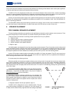
The base monitoring width (also referred to as monitoring angle) is important for both music and film sound reproduction.
Monitoring angles from 45 to 60 degrees are commonly used for proper translation and accurate stereo imaging. While the
stereo base width will become greater in larger rooms or with greater monitoring distances, in rooms where picture is used as
reference the size of the picture will dictate the available width. In general. a stereo base width corresponding to angles of 45
degrees, relative to the left and right loudspeakers, when viewed from the principal seating location, is preferable for mixing
sound with picture. Wider monitoring angles up to 60 degrees (are more common for music mixing). Placement optimization
should also include locating the speakers in such a way as to put all speakers equidistant from the listening position. This time-
aligns the speakers to the monitoring position and improves imaging. A digital delay may be used to achieve similar results.
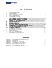
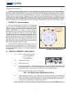
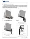
ITU-R BS.775-1 Recommendation
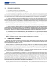
Many professionals find the ITU-R BS.775-1 recommendation
useful as either a final placement solution or as a starting point
from which to work. This recommendation is based on placing the
speakers at equal distances around a 2.5 meter circle with the
height of each speaker at 1.2 meters. The center speaker is
placed directly in front of the listener with the left and right speak-
ers placed 30 degrees on either side of the center speaker.
Placement of the surrounds is somewhat more flexible. The ITU
recommends that the surrounds be placed anywhere between 100
and 120 degrees from the location of the center speaker with 110
degrees being the most common solution. Placing the surrounds
farther behind the mixer (120 to 135 degrees) may cause the sin-
gle enveloping sound field to collapse leaving the listener with two
distinct and seemingly unrelated soundfields.
The ITU-R BS.775-1 placement solution works very well in
critical listening environments where the listening position is
known and is especially effective for those working in applications
like music composition and mixing, sound design, broadcast and
DVD authoring.
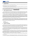
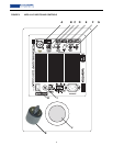
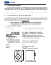
6. INPUTS & CONTROLS (SEE FIGURE 3)
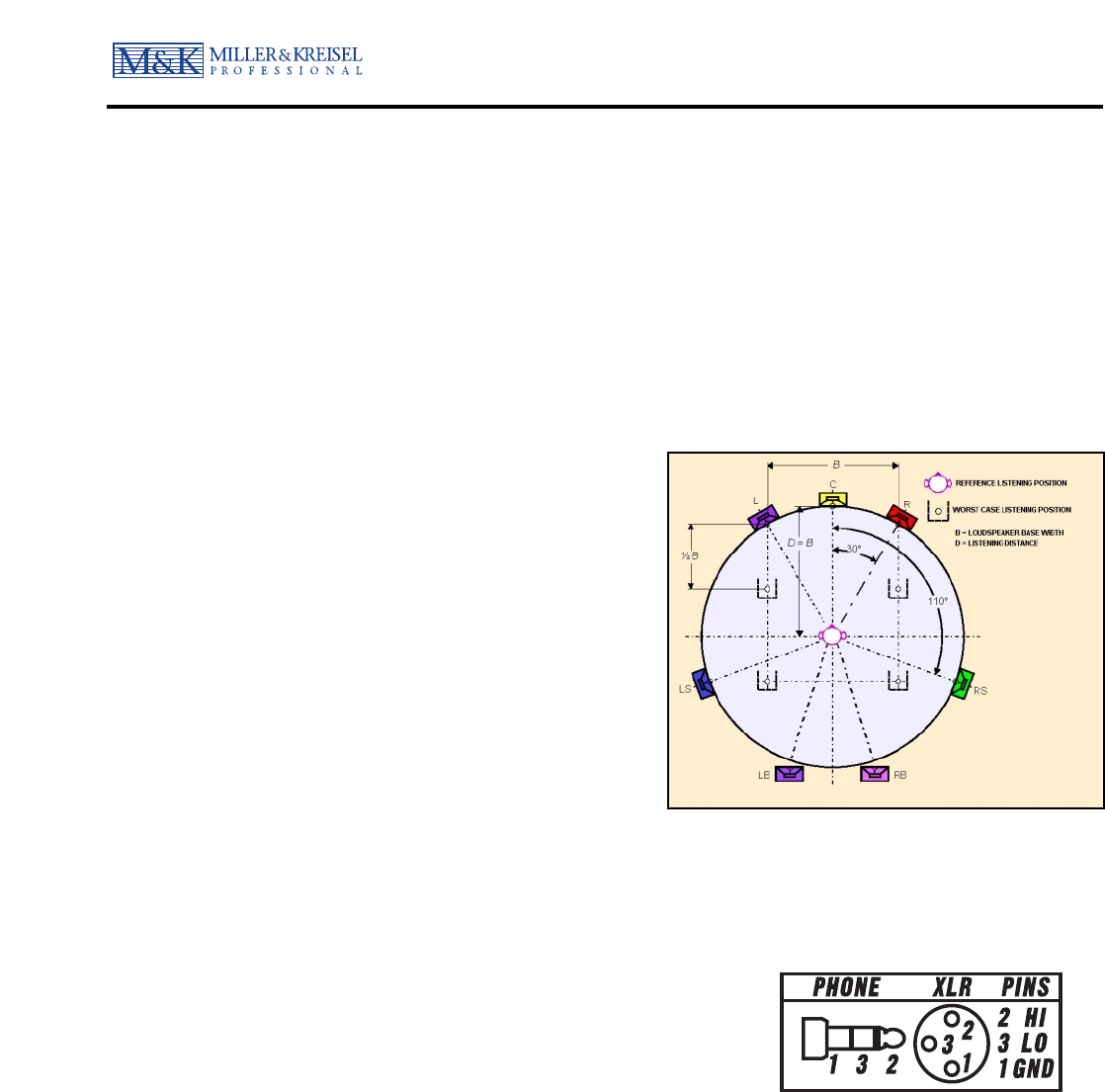
A) XLR - 1/4” (Phone) Balanced Input
• Pin 1 Sleeve (ground)
• Pin 2 Tip (plus)
• Pin 3 Ring (minus).
B) Unbalanced RCA Input
C) Power Indicator LED
D) Input Sensitivity Selector – use the FIXED position when a 200mV referenced signal is delivered to
the XLR input or when a 100mV referenced signal is delivered to the RCA input. In order to use the
variable gain knob (E), the input gain switch must be set to the VARIABLE position.
NOTE: Pink Noise input signal to give a set output SPL:
“Fixed” = 200mV Balanced (100mV unbalanced) gives 91 dB at 1m
“+4dBu” = 1.23V Balanced (615mV unbalanced) gives 91 dB at 1m
E) Variable Input Gain Controller – offers variable gain from –6dB to +6dB relative to the REFERENCE
position. REFERENCE denotes the position that should be used when operating this monitor with
+4dBu referenced input signals. In other words, in variable gain mode the “REF” position on the
control gives the same level as the “+4dBu” switch position.
(Note: This control is only effective when the input gain switch (D) is set to the VARIABLE position.)
FIGURE 2 ITU-R BS.775-1 SPEAKER
PLACEMENT RECOMMENDATION