


Model RG1 Owner’s Manual
Page 10 www.midlandradio.com
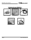
Antenna Considerations
A variety of antennas are available from a number of quality suppliers. It is rec-
ommended you draw upon the advice of your Midland dealer in determining a suitable
antenna for your vessel and range requirements.
In general, communication range is increased by using a high-gain antenna
placed as high as possible above the water line. Antennas should be located away from
metal objects. Antennas should not have excessively long coaxial feed cables.
Antenna Selection and Installation
REGATTA 1 has been designed to accommodate all of the popular marine VHF
antennas. However, the selection and the installation of the antenna is the responsibility
of the user or installer. The FCC has determined that excessive radiation poses a health
risk to people near radio transmitting antennas. Therefore, the antenna used
with this radio should be installed using the following guidelines to insure
a suitable distance between the antenna and persons close by. Small whip antennas (3
dB) or smaller should be installed keeping at least three feet separation distance
between the radiating element and people. Larger antennas (6 dB or 9 dB) should be
installed keeping at least a six foot separation distance. No person should touch the
antenna or come into the separation distance when the radio is transmitting.
CAUTION:
The antenna(s) used for this transmitter must not be co-located or operating in conjunction with any other antenna or transmitter. This device is
approved with emissions having a source-based time-averaging duty factor not exceeding 50%. The safe operating distance between the general
population and the antenna when transmitting is 35 inches. Failure to observe these restrictions will result in exceeding the FCC RF exposure limits.
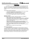
Installing the REGATTA 1
After you have carefully considered the various factors affecting your choice of
location, position the radio (with the bracket, microphone, power cord, antenna and any
auxiliary cables installed) into the selected location to assure there
is no interference with the surrounding items.
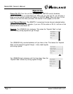
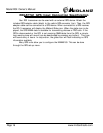
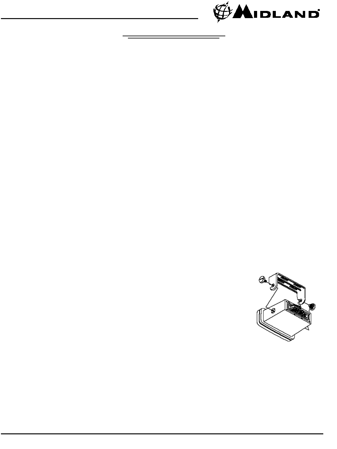
Mark the location of the mounting bracket. Remove the
bracket from the radio and use it as a template to mark the holes
to be drilled for the mounting hardware. Drill the holes and mount
the bracket with hardware compatible with the material of the
mounting surface. Then attach the
radio to the mounting bracket
using the included knobs.
Connect the red wire of the supplied power cord to the positive (+) battery supply.
Connect the black wire of the power cord to the negative (–) battery supply. The power
cord is equipped with a fuse to protect the radio. Use only a 7 ampere fast blow fuse
for replacement. Connect the power cord to the keyed connector on the power "pigtail".
Connect the antenna and all other auxiliary cables and accessories. Install the radio in
the mounting bracket and connect all cables and accessories to the appropriate jacks
and connectors.
Installation cont...
Installation cont...
Note: Do not use any other mounting
knobs than the ones enclosed.
Do not insert the knobs without
attaching the bracket.