Model GXT5000 Series
Page 4 www.midlandradio.com
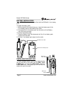
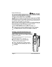
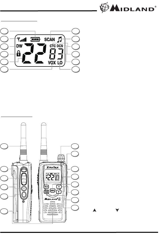
CONTROLS
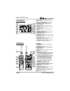
LCD DISPLAY
1. BATTERY METER – Indicates the battery
level.
2. SIGNAL STRENGTH METER – Indicates the
transmit and receive signal strength.
3. DUAL WATCH ICON – Indicates the Dual
Watch function is on.
4. KEY LOCK ICON – Indicates KEY LOCK
mode is on.
5. CHANNEL NUMBER – Changes from 1~22 on
GMRS/FRS band.
6. VOX ICON – Indicates when VOX mode is
active.
7. CHANNEL SCAN ICON – Indicates when the
Channel Scan function is on.
8. ROGER BEEP ICON – Indicates when the
Roger Beep function is on.
9. CTCSS ICON – Indicates the radio is set with a
CTCSS Privacy Code.
10. DCS ICON – Indicates the radio is set with a
DCS Privacy Code.
11. PRIVACY CODE – Indicates Privacy Code
selected by user (oF~38/oF~83).
12. TRANSMIT POWER LEVEL LO ICON –
Indicates TX Power is at Lo setting.
13. ANTENNA
14. SOS Siren Button – Press and hold to turn
on the Siren.
15. PTT Button – Press and hold to transmit
voice communication.
16. MONITOR Button – Press and hold to enter
MONITOR mode.
17. CALL Button – Press to send a CALLAlert
signal.
18. SPEAKER – Built-in speaker.
19. POWER/VOLUME KNOB – Turn clockwise to
turn the power on and increase the volume
level. Turn counter-clockwise to decrease the
volume level and turn the power off.
20.
TRANSMIT (TX)/RECEIVE (RX) LED Indicator
– Indicates RED when the radio is in TX
mode. Indicates GREEN when the radio is
receiving the correct Channel and Privacy
Code, or when the Privacy Code is set to
OFF. Indicates ORANGE when the radio is
receiving the correct channel but wrong
Privacy Code.
21. EXTERNAL SPEAKER/MIC JACK.
22. TRANSMIT POWER HI/LO Button – Press to
toggle between Transmit Power HI and LO.
23. MENU Button – Press to access
Menu mode.
24. UP and DOWN Button – Press to make
the adjustments in MENU mode.
25. SCAN/LOCK Button – Press to enter SCAN
mode. Press and hold to turn KEY LOCK
on/off.
26. MIC – Built-in microphone.
1
12
11
10
9
8
7
6
5
4
3
2
13
14
24
23
22
21
20
19
18
17
16
15
26
25


