


#
Power Connector Wiring
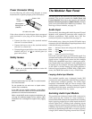
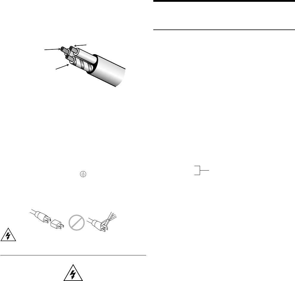
Use the following AC cable wiring diagram to create
international or special-purpose power connectors:
brown = hot
blue =
neutral
yellow/green =
earth ground
(chassis)
AC cable color code
If the colors referred to in the diagram don't correspond
to the terminals in your plug, use the following guide-
lines:
• Connect the blue wire to the terminal marked
with an N or colored black.
• Connect the brown wire to the terminal marked
with an L or colored red.
• Connect the green and yellow wire to the terminal
marked with an E (or ) or colored green (or
green and yellow).
Safety Issues
Do not use a ground-lifting adapter or cut the AC
cable ground pin.
Keep all liquids away from the UM-P to avoid hazards
from electrical shock.
Do not operate the unit with worn or frayed cables;
replace them immediately.
If the UM-P will be installed outdoors contact Meyer
Sound for information about the rain hood and weather
protection for the drivers and electronics.
While a single UM-P can be hung by its handle bars, do
not hang any additional weight from the cabinet. UM-P
handle bars are not designed to support heavy rigging
loads.
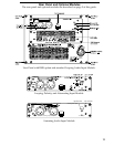
The Modular Rear Panel
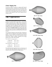
The rear panel of the UM-P has two slots for processor
modules. The top slot contains the Audio Input and
Control Module; the bottom slot contains the optional
Remote Monitoring System™ (RMS) Module. A blank
plate covers the bottom slot if RMS is not installed. For
drawings of these modules, see page 13.
Audio Input
There are three, interchangeable Audio Input and Control
Modules with optimized connectors and controls for
different applications. Each module has a 24V Fan
connector to power an optional fan (see page 7).
Each module uses a three-pin, female XLR audio input
connector with a 10 kΩ balanced input impedance wired
with the following convention:
Pin 1 — 220 kΩ to chassis and earth ground (ESD clamped)
Pin 2 — Signal
Pin 3 — Signal
Case — Earth (AC) ground and chassis
Pins 2 and 3 carry the input as a differential signal. Use
standard audio cables with XLR connectors for balanced
signal sources. A single audio source can drive multiple
UM-Ps with a paralleled input loop, creating an unbuf-
fered hardwired loop connection, with negligible loss
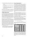
in signal level. For example, since the input impedance
of one UM-P is 10 kΩ, looping 20 UM-Ps produces a
balanced input impedance of 500Ω. With a 150Ω audio
source, the 500Ω load results in only a 2.28 dB loss.
Looping Audio Input Module
This standard module uses a balanced, female XLR
connector for audio input and a male XLR loop connector
to interconnect multiple speakers. The audio input
connector is hardwired with pin 2 hot to comply with
audio industry standards. The loop connector, wired in
parallel to the audio input, transmits the input signal if
the UM-P is turned off for any reason.
Summing Audio Input Module
This module has a balanced, female XLR connector for
audio input but has, instead of a loop connector, a
second female XLR connector that functions as a summing
input. Applying a signal to one of the inputs results in a
normal signal level. Utilizing both summing inputs
creates a correctly summed mono signal with each input
6 dB below the level of a single input. This is an effective
method for distributing both sides of a stereo signal to
a single UM-P without requiring external level control.
Differential Inputs