


!
Introduction
The Integrated Design
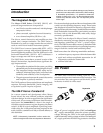
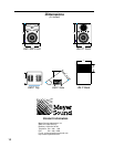
The Meyer UM-P Series (UM-100P, UM-1P) self-
powered stage monitors are composed of:
• one 12-inch cone driver and one 3-inch diaphragm
compression driver;
• phase-corrected, optimized control electronics;
• a two-channel amplifier (350 W
rms/ch).
The drivers, control electronics, and amplifier are inte-
grated into a compact enclosure. The UM-P Series is
intended to be used as a stage monitor but can also be
used as a mid-hi and musical instrument speaker.
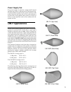
The UM-1P horn’s narrow beamwidth (45°H x 45°V)
permits precise coverage with minimal interaction be-
tween neighboring monitors. The UM-100P horn’s wide
horizontal beamwidth (100°H x 40°V) addresses a
larger coverage area with fewer speakers.
The UM-P Series, more than a powered version of the
Meyer Ultra-monitor, implements these significant de-
sign improvements:
• The amplifier is optimized for the system, providing
substantial power without endangering the drivers.
• The integrated design simplifies setup and in-
stallation, eliminates amp racks, and extends the
durability and reliability of the loudspeaker.
• The gain structure between the control electronics
and amplifier is perfectly matched.
The UM-P produces flat acoustical phase and amplitude
response, full-range bandwidth, precise imaging, and
exceptional system impulse response.
The UM-P Horns: Constant-Q
In a recent research and development effort, Meyer
Sound solved the most difficult problems associated
with horn design. In order to appreciate the significance
of this work, it is necessary to define an often misunder-
stood term: the beamwidth of a horn is the angle at
which the sound pressure at a given frequency decreases
to half (–6 dB) its on-axis amplitude. Specifying beam-
width using the –6 dB points has been proposed as the
audio industry standard and Meyer Sound adheres to
this definition.
NOTE: Unfortunately, beamwidth is often used to de-
scribe the angle at which the sound pressure decreased
10 dB from its on-axis amplitude because many listeners
perceive this as a decrease to half the SPL. When reading
a beamwidth specification, it is essential to determine
whether it refers to the 6 or 10 dB points because they
indicate very different results: the 10 dB points yield a
wider angle.
Previous technologies produced horns whose beamwidth
varied over the operating frequency range. These horns
also displayed nonuniform frequency response within,
and significant side lobe energy outside their beamwidth.
Both undesirable characteristics, particularly prevalent
for horns with a wide beamwidth, make array design
extremely uproblemactic
The UM-P was developed in Meyer Sound’s anechoic
chamber by measuring coverage patterns using angular
and frequency resolutions of 1° and
1
¦36 octave, respec-
tively. The UM-P horns exhibit constant-Q: the beamwidth
remains consistent across the horn’s operating frequency
range in both the vertical and horizontal planes.
Both horns share the following remarkable attributes:
• uniform frequency response within the beamwidth
• rapid and uniform amplitude attenuation for all
frequencies outside the beamwidth
• minimal side lobes
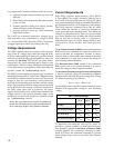
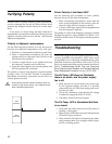
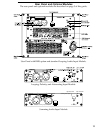
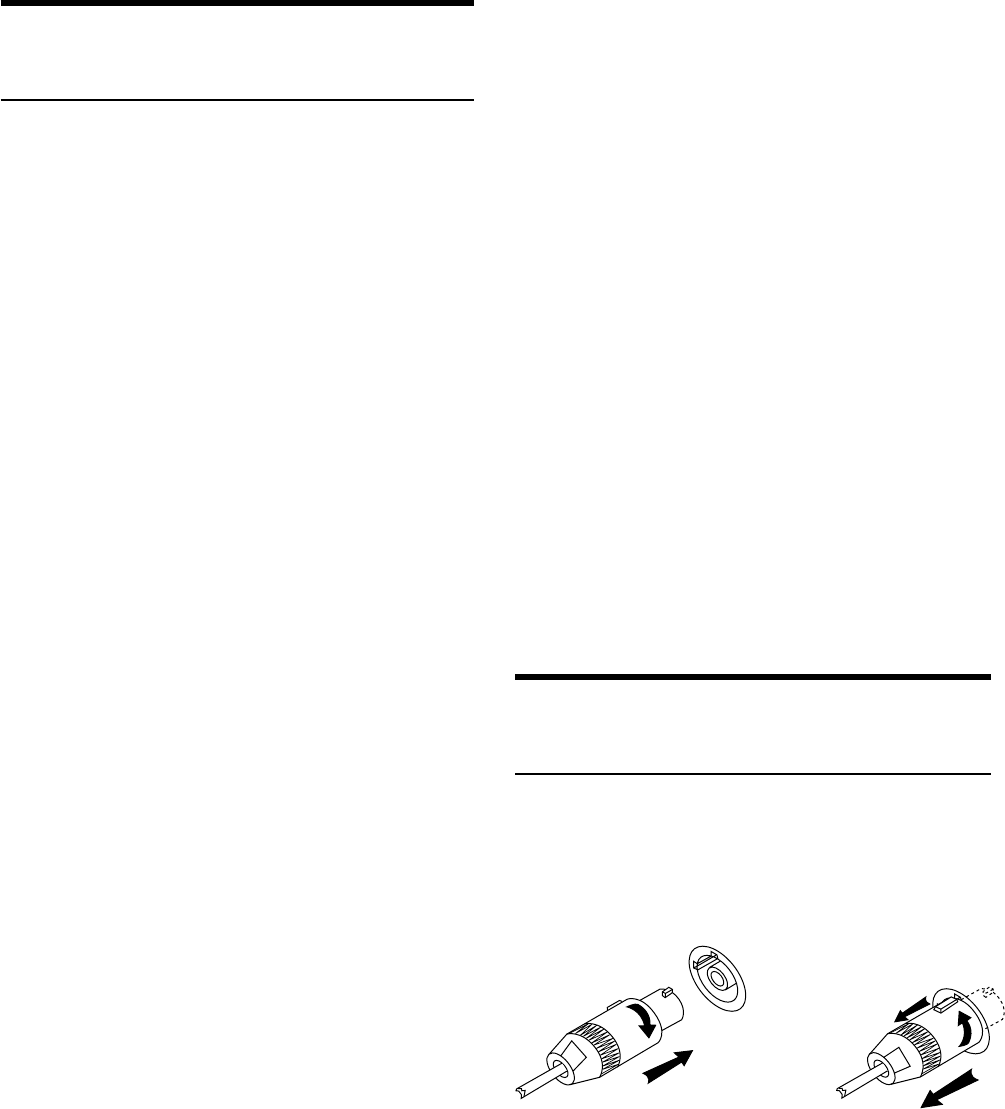
AC Power
The UM-P uses a PowerCon locking 3-pole AC mains
connector that prevents inadvertent disconnection. The
unit must have the correct power cord for the AC power
in the area in which it will be used.
When AC power is applied to the UM-P, an Intelligent
AC
tm
supply automatically selects the correct operating
voltage, allowing the UM-P to be used internationally
without manually setting voltage switches. The Intelligent
AC supply performs the following protective functions
Engagement
2
1
2
1
3
Separation