


"
to compensate for hostile conditions on the AC mains:
• suppresses high voltage transients up to several
kilovolts
• filters EMI (radio frequencies and noise present
on the AC line)
• sustains operation during low-voltage periods,
which minimizes audio discontinuity
• provides soft-start power-up, which eliminates
high inrush current
The UM-P can withstand continuous voltages up to
264V and allows any combination of voltage to GND
(i.e. Neutral-Hot-GND, Hot-Hot-GND). Continuous
voltages higher than 264V may damage the unit.
Voltage Requirements
The UM-P operates safely and without audio disconti-
nuity if the AC voltage stays within the range 88–264V,
47–63 Hz. After applying AC power, the system is muted
while the circuitry charges up and stabilizes. After two
seconds, the On/Temp. LED on the user panel illumi-
nates green, the system unmutes and is ready to pass
audio signals. If the On/Temp. LED does not illuminate
or the system does not respond to audio input after ten
seconds, consult the Troubleshooting section.
The UM-P’s power supply uses stored energy to continue
functioning for about 10 AC cycles if the voltage decreases
below 88V (a condition known as brownout). The precise
length of time the unit functions during brownout
depends on the operating level and how low the voltage
drops. The unit turns off if the voltage does not increase
above 88V before the storage circuits are depleted. If
the UM-P shuts down due to brownout, the power
supply automatically turns on after three seconds if the
voltage returns to the normal operating range. If the
UM-P does not turn back on after ten seconds, consult
the Troubleshooting section.
NOTE: We recommend that the supply be operated at
least a few volts away from the upper and lower bounds
of the operating range to avoid possible shutdown.
Current Requirements
Each UM-P requires approximately 3Arms @115V
(1.5Arms@230V) for proper operation, allowing up to
five UM-Ps to be powered from one 15A circuit. How-
ever, we recommend powering no more than three UM-Ps
per 15A branch to allow a 30% margin for peak voltages.
The UM-P presents a dynamic load to the AC mains
which causes the amount of current to fluctuate be-
tween quiet and loud operating levels. This affects the
number of UM-Ps that can be used for a given breaker
type. Since different types of cables and circuit breakers
heat up and trip at varying rates, it is essential to
understand the types of current ratings and how they
correspond to circuit breaker and cable specifica-
tions.
The maximum continuous RMS current is the maximum
RMS current over a duration of at least 10 seconds. It is
used to calculate the temperature increase in cables,
which is used to select cables that conform to electrical
code standards. It is also used to select the rating for
slow-reacting thermal breakers.
The maximum burst RMS current is the maximum
RMS current over a one second duration. It is used to
select the rating for most magnetic breakers.
The maximum instantaneous peak current during burst
is used to select the rating for fast-reacting magnetic
breakers and to calculate the peak voltage drop in long
AC cables according to the formula
Vpk
drop
= Ipk x Rtotal cable
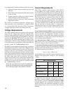
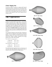
Use the table below as a guide to select cables and circuit
breakers with appropriate ratings for your operating
voltage.
sgnitaRtnerruCP-MU
V511 V032 V001
SMReldI
A52.0
SMR
A31.0
SMR
A3.0
SMR
SMRsuounitnoC.xaM
A8.2
SMR
A4.1
SMR
A2.3
SMR
SMRtsruB.xaM
A2.3
SMR
A6.1
SMR
A7.3
SMR
tsruBgniruDkaeP.xaM
A0.5
KAEP
A5.2
KAEP
A8.5
KAEP
To determine the minimum total service power re-
quired by a system of UM-P, or other Meyer self-pow-
ered speakers, add their maximum continuous RMS
currents together. We recommend allowing an addi-
tional 30% above the minimum amperage to prevent
peak voltage drops at the service entry and nuisance
tripping.