MINA OPERATING INSTRUCTIONS
31
above them, whether they are flown or ground-
stacked, and other factors. MAPP Online Pro is rec-
ommended for determining the optimum splay angles
for loudspeakers and coverage pattern of the array.
NOTE: Optimal acoustical performance for
MINA arrays is achieved by using the appropri-
ate number of units and splay angles to meet the
coverage requirements of the venue. Use the design
guidelines for MINA arrays in Chapter 4, “Line Arrays
and System Integration” along with MAPP Online Pro
to verify designs and rigging configurations.
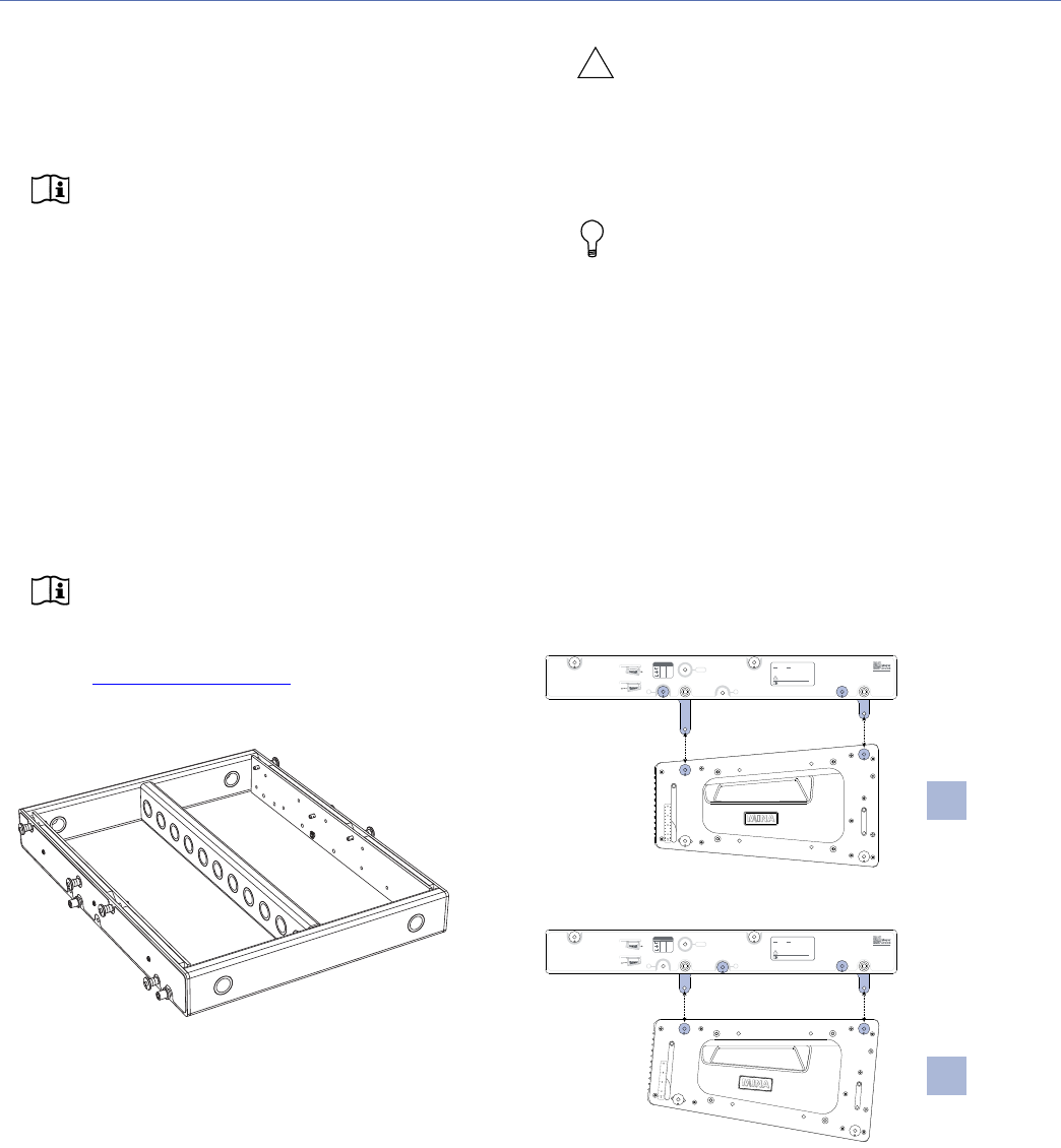
MG-MINA GRID
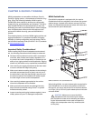
The MG-MINA grid flies MINA arrays of up to 12 cabinets at
a 7:1 safety ratio, or up to 16 cabinets at a 5:1 safety ratio.
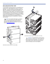
The grid, which can also be used for groundstacking arrays,
accommodates a variety of pickup configurations with four
side pickup points and 11 center pickup points.
NOTE: For complete information on configura-
tion and load ratings for the MG-MINA, as well
as other MINA rigging accessories, refer to the
MG-MINA Assembly Guide (PN 05.207.101.01) avail-
able at www.meyersound.com
.
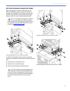
The MG-MINA grid has four captive links, two per side, that
attach to the top MINA in flown arrays. The configuration of
the links and orientation of the grid (for either maximum
uptilt or maximum downtilt) determine the angle of the
attached MINA. The grid links are easily stowed for transport
and groundstacked configurations.
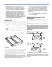
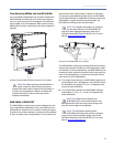
The MG-MINA grid includes eight (1/4 by 0.90-inch) quick-
release pins: four for securing the four grid links, and four for
securing MINA groundstacks to the top of the grid.
CAUTION: Always use the quick-release pins
included with the MG-MINA grid to secure its
links, as well as to secure groundstacked MINAs to
the grid. Do not use the quick-release pins included
with MINA in the grid as they are shorter and will not
lock in place.
TIP: The MG-MINA grid can travel installed on
top of MINA stacks.
MG-MINA Grid Orientations for Flown
Configurations
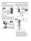
The orientation of the MG-MINA grid determines the maxi-
mum downtilt and maximum uptilt for flown arrays.
MG-MINA Oriented for Maximum Array Downtilt
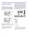
When the MG-MINA grid is oriented with the links toward
the front of the flown loudspeakers, the grid provides maxi-
mum downtilt for the flown array (when tilting the grid). The
label on the MG-MINA shows this configuration as “Maxi-
mum Downtilt.”
With the maximum downtilt orientation, the MINA at the top
of the array can be attached to the grid at 0 and –5 degree
(downtilt).
MG-MINA Grid
MG-MINA Grid, Maximum Downtilt Orientation, 0 and –5 Degrees
!
MAXIMUM UP-TILT
MAXIMUM DOWN-TILT
STOW
B
A
GROUND STACKGROUND STACK
Berkeley, CA
MG-MINA
SEE MG-MINA ASSEMBLY GUIDE FOR ADDITIONAL LOAD
RATINGS AND RIGGING SAFETY INFORMATION.
CAUTION: DO NOT EXCEED LOAD RATING
PRECAUTION: NO EXCEDER LIMITE DE CARGA
ATTENTION: N'EXCEDEZ PAS L'ESTIMATION DE CHARGE
VORSICHT: UBERSTEIGEN SIE NICHT LAST BEWERTUNG
5:1 7:1
693 lbs
314.3 kg
(16 MINA)
495 lbs
224.5 kg
(12 MINA)
LOAD RATINGS: FLOWN
A0º
B-5º
A-10º
MINA FLOWN
POSITIONS
RESULT
ANGLE
–5°
0°


