


6
Installation
It is recommended that a professional who is skilled in all
aspects of installation and operation install the
MCC602TM and any associated mobile audio equipment.
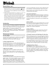
Amplifier Ventilation
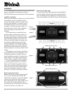
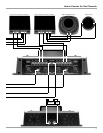
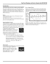
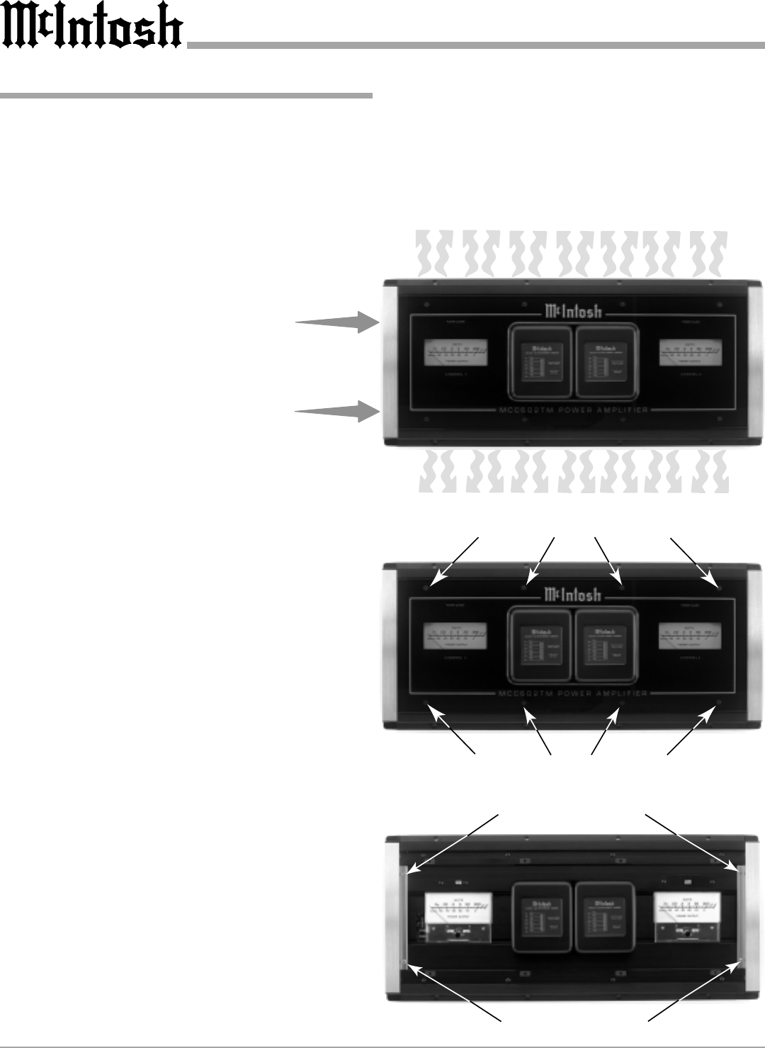
Always provide adequate ventilation for the MCC602TM.
The amplifier requires an adequate airflow
into the cooling fans, which are located on the
left side of the amplifier. The warm air exits
the amplifier through vents on the heatsinks.
See figure 1. Be sure to provide at least 1-1/2
inches clearance in front of the cooling fans
and 1 inch clearance at the sides of the
heatsinks.
The cooling fans are controlled by tem-
perature sensors, attached to the interior of
the tunnel. The fans are normally off. If the
program material contains sustained loud pas-
sages demanding high power, the fans will
turn-on to increase cooling. If cooling is still
not sufficient, additional heating will shut
down the amplifiers internal power supply
completely and the Power Guard LEDs will
light. The fans will continue to run and once
normal temperature is restored, operation will
resume.
The amplifier can be mounted vertically or
horizontally and may be located under a seat
if adequate clearance is available. The pre-
ferred installation method is to mount the am-
plifier directly to the vehicle main frame us-
ing the hardware supplied with the amplifier.
It is not recommended that the amplifier
be mounted under the hood or in a location
where it will be directly exposed to the ele-
ments. The openings in the fan housings and
heat tunnel vents can allow internal compo-
nents to be damaged by exposure to water,
chemicals or any form of road dust or debris.
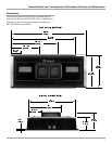
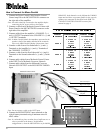
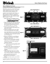
Removing the Glass Panel
Remove the eight hex bolts with the supplied
3/32 hex key from the MCC602TM Top
Glass Panel. See figure 2. Attach the supplied
suction cup to either side of the top glass
panel and carefully raise it high enough to put
your hand under. Temporarily place the re-
moved glass panel in a safe place, remove the
suction cup and save it for future use.
Remove Top Cover Screws
Remove Top Cover Screws
Figure 2
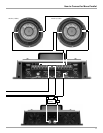
Remove End Cap Screws
Remove End Cap Screws
Figure 3
Warm Air
Warm Air
Cool Air
Figure 1
Cool Air
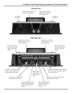
Removing the End Caps
To access the MCC602TM Connecting Terminal Blocks,
remove the Glass Panel first (the above step) and then re-
move the Phillips Screws holding the End Caps on both
sides of the amplifier and lift the end caps off. See figure 3.