


10
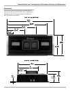
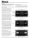
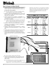
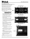
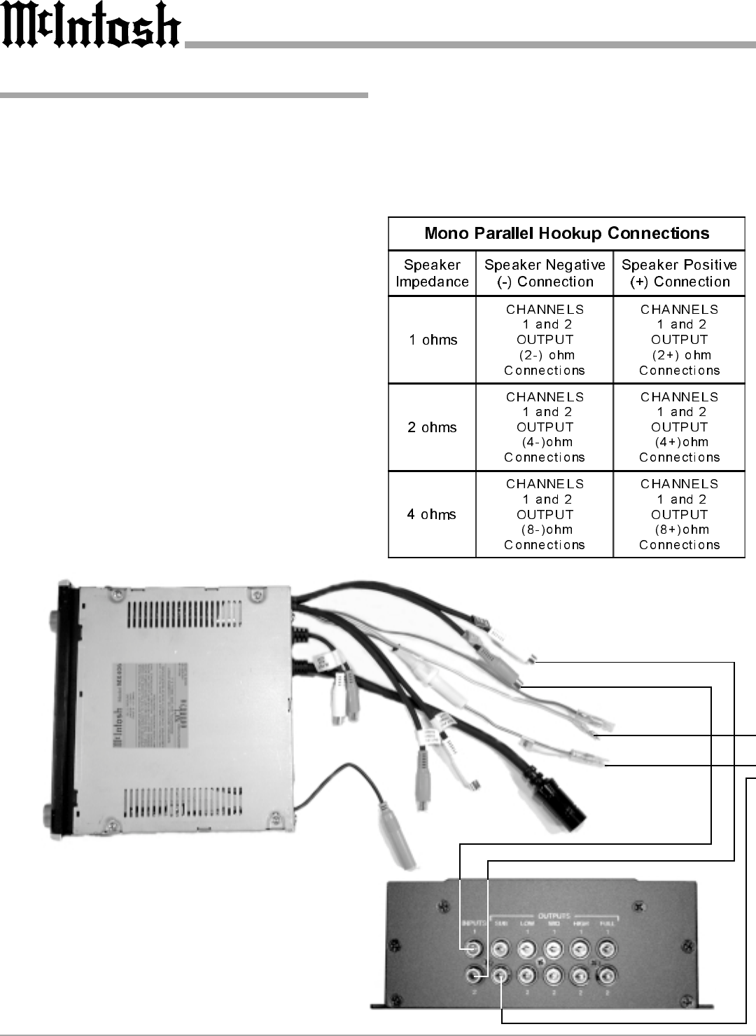
How to Connect for Mono Parallel
1. Connect the Power Control Cable from the Control
Center Amp ON to the MCC602TM ON connector on
the right side of the amplifier.
Note: All cables should be connected to the amplifier before
connecting the DC power cables to the battery.
2. Connect a cable from a McIntosh Control Center with
Power Guard to the MCC602TM PG connector on the
right side of the amplifier.
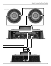
3. Connect cables from the amplifiers CHANNEL 2 (+)
and (-) OUTPUT terminals to the CHANNEL 1 (+) and
(-) OUTPUT terminals.
Note: In Mono Parallel Mode, the impedance presented to the
speaker is half of the number marked on the terminals,
refer to the Mono Parallel Hookup Connections chart.
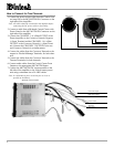
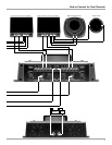
4. Connect a cable from a first Subwoofers (+) and (-)
Terminals to the Amplifiers (+) and (-) Terminals of
the CHANNEL 2 OUTPUT.
5. Connect a cable from the first Subwoofers (+) and (-)
Terminals to the Second subwoofers (+) and (-) Termi-
nals.
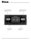
6. Connect audio cables from a McIntosh Control Center
to the INPUTs of a McIntosh Crossover Network.
7. Connect audio cables from the McIntosh Crossover
Network SUB OUTPUT to the MCC602TM 2/MONO
Input.
Note: Do not connect a cable to the LEFT input.
8. Connect the MCC602TM DC input terminals to the
vehicle battery terminals using a minimum size of 4
AWG cables.
Note: It is advisable to place an inline fuse of sufficient size as
close as possible to the battery. An alternative
configuration is, when the MCC602TM is set for MONO
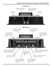
McIntosh Crossover Network
McIntosh Control Center
Left Front Output
Right Front Output
Amp ON
(blue/white)
Power Guard
(orange)
PARALLEL, both channels can be fed from the 2/MONO
Input and each drive a separate speaker. In this case the
speakers are connected as described in the HOW TO
CONNECT FOR TWO CHANNEL section of this
manual on page 8.