


3
Customer Service
Technical Assistance
Please Take A Moment
Thank You
Copyright 2000 ã by McIntosh Laboratory, Inc.
The serial number, purchase date and McIntosh dealer
name are important to you for possible insurance claim or
future service. The spaces below have been provided for
you to record that information:
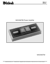
Your decision to own this McIntosh MCC602TM Two
Channel Power Amplifier ranks you at the very top among
discriminating music listeners. You now have The Best.
The McIntosh dedication to Quality, is assurance that
you will receive many years of musical enjoyment from
this unit.
Please take a short time to read the information in this
manual. We want you to be as familiar as possible with all
the features and functions of your new McIntosh.
Serial Number:
Purchase Date:
Dealer Name:
If it is determined that your McIntosh product is in need of
repair, you can return it to your dealer. You can also return
it to the McIntosh Laboratory Service Repair department.
For assistance on factory repair return procedure, contact
the McIntosh Repair Department at:
McIntosh Laboratory, Inc.
2 Chambers Street
Binghamton, New York 13903
Phone: 607-723-3515
Fax: 607-723-1917
If at any time you have questions about your McIntosh
product, contact your McIntosh dealer who is familiar with
your McIntosh equipment and any other brands that may
be part of your system. If you or your dealer wish addi-
tional help concerning a suspected problem, you can re-
ceive technical assistance for all McIntosh products at:
McIntosh Laboratory, Inc.
2 Chambers Street
Binghamton, New York 13903
Phone: 607-723-1545
Fax: 607-723-3636
Safety Instructions ............................................................. 2
Thank You.......................................................................... 3
Please Take a Moment ....................................................... 3
Customer Service............................................................... 3
Table of Contents............................................................... 3
General Notes .................................................................... 3
Introduction ....................................................................... 4
Performance Features ........................................................ 4
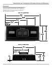
Dimensions ........................................................................ 5
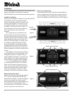
Installation ......................................................................... 6
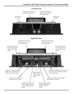
Side Panel Cooling, Connections and Switch ................... 7
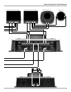
How to Connect for Two Channels ................................... 8
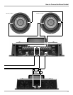
How to Connect for Mono Parallel ................................. 10
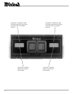
Top Panel Displays .......................................................... 12
How to Operate................................................................ 13
How to Replace the Fuses ............................................... 14
Technical Description and Block Diagrams .................... 15
Specifications .................................................................. 18
Packing Instruction .......................................................... 19
Table of Contents
General Notes
1. Do not connect the Amplifier Speaker Negative Terminal
Connection directly to the Vehicle Chassis. Failure to observe
this could result in damage to your Amplifier.
2. For additional connection information, refer to the owners
manual(s) for any component(s) connected to the
MCC602TM Amplifier.
3. There is a built-in turn on delay which will mute the speaker
outputs for approximately two seconds when the amplifier is
turned on.
4. It is very important that loudspeaker cables of adequate size
be used in your music system, to ensure that there will be no
power loss or heating. Use at least 14 Gauge (AWG) wire size
or larger. The speaker output terminals are large enough to
accept 12 Gage wire.
5. It is advisable to place an in-line fuse as close as possible to
the battery.
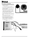
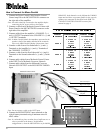
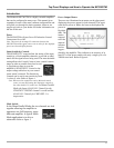
6. The pin configuration for the XLR Balanced Input connectors
on the MCC602TM. Refer to the diagram for connections.
PIN 1: Shield or ground
PIN 2: (+) input
PIN 3: (-) input
7. The MCC602TM can accept speaker
level inputs at its Balanced Input Jacks.
Refer to the diagram for connection.
PIN 1: No connection
PIN 2: Power Amplifier Output Connection (+) from the
Control Center
PIN 3: Power Amplifier Output Connection (-) from the
Control Center