


16
McIntosh Laboratory, the company who introduced the
world’s first amplifier that could be called “High Fidelity”,
has done it again. The McIntosh engineering staff has cre-
ated a power amplifier without compromise, using the most
advanced McIntosh circuit design concepts.
A continuous average power output rating of 400 watts
and with an output current of greater than 100 amperes per
channel, makes this not only the most advanced, but also
one of the most powerful amplifiers McIntosh has ever
manufactured. The distortion limits for the MC402 are no
more than 0.005% at rated power output for all frequencies
from 20Hz to 20,000Hz. Typical performance at mid fre-
quencies is less than 0.002%. The true distortion readings
on the MC402 are so low, it takes special measuring tech-
niques to make accurate readings. The MC402 can deliver
the best possible performance from any type of high qual-
ity Loudspeaker system.
Creating an amplifier with this level of performance did
not come easily. Many months of design, testing and mea-
suring were required. Extensive controlled listening tests,
the ultimate form of measuring, were made before the final
design was accepted.
Design Philosophy
The design philosophy incorporated in the MC402 in-
volved several different techniques, all based on sound sci-
entific logic. Every stage of voltage or current amplifica-
tion must be as linear as possible prior to the use of nega-
tive feedback. McIntosh engineers know how to properly
design negative feedback circuits so they contribute to the
extremely low distortion performance expected from a
McIntosh amplifier. The typical McIntosh owner would
never accept the approximately 100 times higher distortion
of many non-feedback designs.
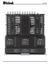
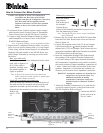
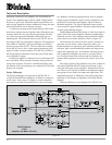
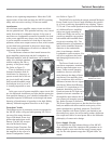
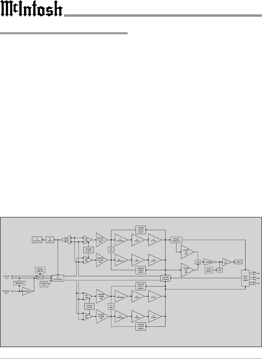
Double Balanced Push-Pull design is used from input to
output. Each half of the amplifier contains complimentary
balanced circuitry. The resulting double balanced configu-
ration cancels even order distortion. Refer to figure 20.
All transistors are selected to have nearly constant cur-
rent gain over the entire current range they must cover.
Output transistors in particular, have matched uniform cur-
rent gain, high current bandwidth product and large active
region safe operating area. An automatic tracking bias sys-
tem completely eliminates any trace of crossover distor-
tion. Precision metal film resistors and low dielectric ab-
sorption film capacitors are used in all critical circuit loca-
tions.
The output signals of the balanced circuit are coupled in
the unique McIntosh MC402 Output Autoformer. It pro-
vides low distortion power transfer at frequencies from be-
low 20Hz to well beyond 20,000Hz with optimum imped-
ance points of two ohms, four ohms and eight ohms. The
unequaled expertise of McIntosh in the design and manu-
facturing of autoformers is legendary in the high fidelity
industry.
The high efficiency circuit design of the MC402 con-
Technical Description
Block Diagram
of the
Amplifier and Meter Circuitry
Figure 20