


12
Cover
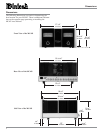
Mounting
Screw
Locations
Cover
Mounting
Screw
Locations
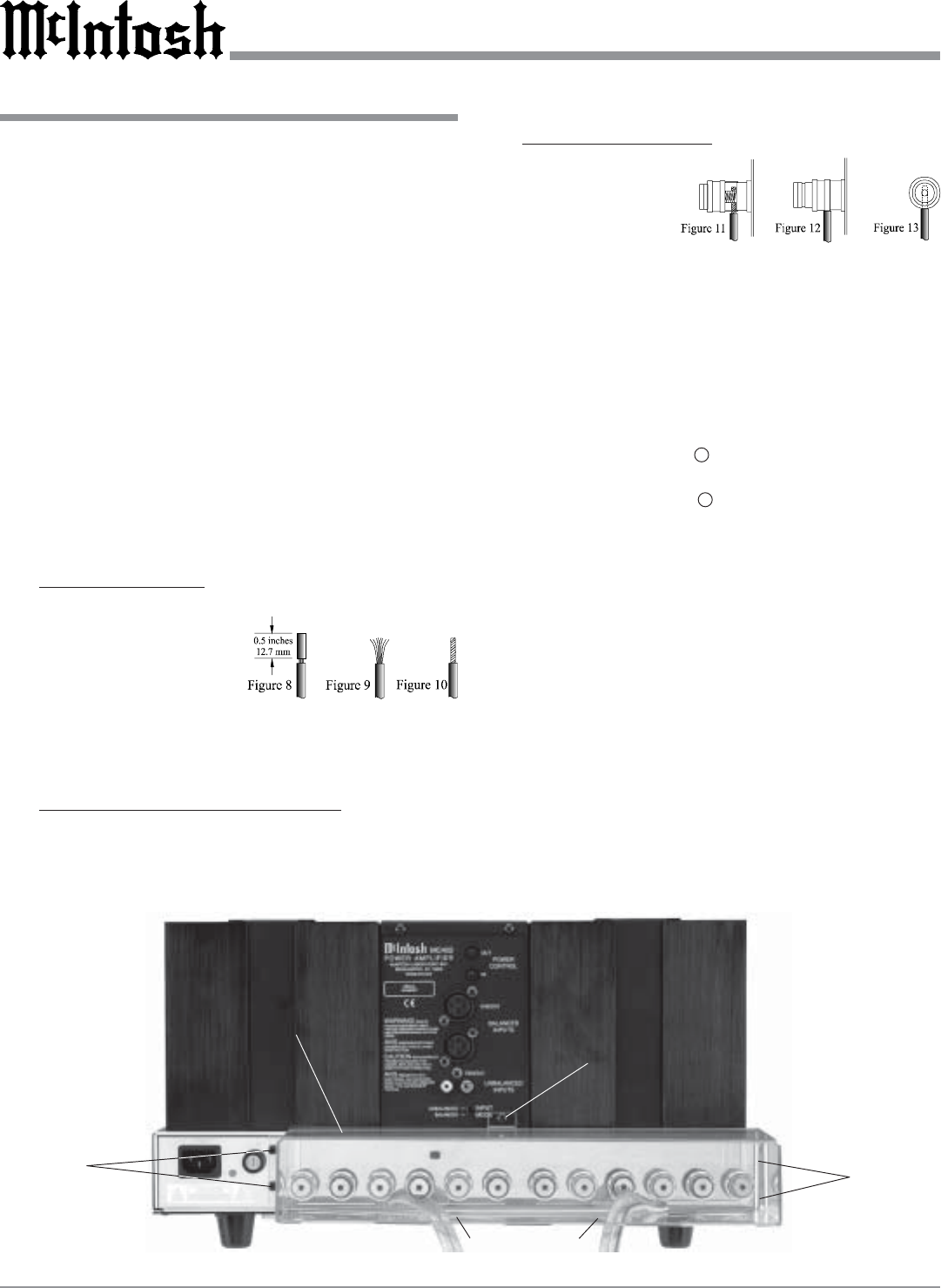
Terminal
Connections
Cover
Cable Openings
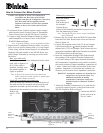
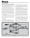
Figure 14
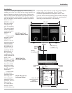
Cover
Mounting
Screw
Location
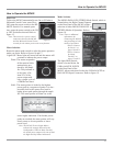
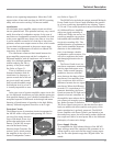
Banana plug connection:
Insert the banana
plug into the
hole at the top of
the terminal.
Tighten the top
portion of the terminal post and the set screw to se-
cure the banana plug in place.
Note: The Banana Plugs are for use in the United States
and Canada only.
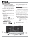
4. Remove the five screws from the MC402 Chassis Rear
Panel and Left Side. Retain these screws for later use.
Refer to figure 14.
5. Connect the prepared twelve inch (30.48 cm) Jumper
Cable between the two - Output terminals and the
thirteen inch (33.02 cm) Jumper Cable between the two
appropriate Impedance + Output Terminal as outlined
in the chart located on the next page.
6. Insert the Loudspeaker Hookup Cable Ends through
the openings of the supplied Terminal Connections
Cover and connect to the output terminals that match
the Loudspeakers’ Impedance, being careful to observe
the correct polarities. Output impedance connections of
1 ohms, 2 ohms and 4 ohms are provided. If the Loud-
speakers’ Impedance is in-between the available con-
nections, use the nearest lower impedance connection.
WARNING: Loudspeaker terminals are hazardous live
and present a risk of electric shock. For
additional instruction on making
Loudspeaker Connections contact your
McIntosh Dealer or McIntosh Technical
Support.
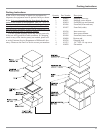
7. Attach the Terminal Connections Cover, with the five
previously removed screws, to the Rear Panel of the
MC402 Amplifier. Refer to figure 7.
8. Connect the MC402
power cord to an ac-
tive AC outlet.
Caution: The supplied AC Power Cord should not be
connected to the Rear Panel of the MC402
Amplifier until after the Loudspeaker Connections
have been made and the supplied protective
Terminal Connections Cover has been installed.
Failure to observe this could result in Electric
Shock.
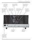
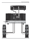
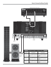
1. For Remote Power Control, connect a power control
cable from the Audio Control Center or Preamplifier
Power Control Out to the MC402 Power Control In.
2. Connect a cable from the Balanced Output of a McIn-
tosh Preamplifier or Control Center to the MC402
R/MONO Balanced Input.
Note: An optional hookup is to use an unbalanced cable.
3. Prepare three Loudspeaker Hookup Cables, one twelve
inch (30.48 cm) and one thirteen inch (33.02 cm) Jumper
Cables, along with the desired length in a Loudspeaker
Hookup Cable that attaches to the MC402 Power Am-
plifier Output Terminals by choosing one of the meth-
ods below:
Bare wire cable ends:
Carefully remove sufficient insulation from the cable
ends, refer to figures 8, 9
& 10. If the cable is
stranded, carefully twist
the strands together as
tightly as possible.
Note: If desired, the twisted ends can be tinned with
solder to keep the strands together, or attach spade
lug and/or banana connector.
Spade lug or prepared wire connection:
Insert the spade lug connector or prepared section of
the cable end into the terminal side access hole, and
tighten the terminal cap until the cable is firmly
clamped into the terminal so the wires cannot slip out.
Refer to fig-
ures 11, 12 &
13.
How to Connect for Mono Parallel