


15
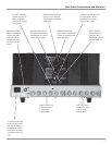
How to Operate the MC402
How to Operate the MC402
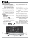
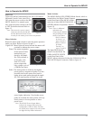
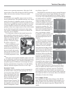
Power On
To have the MC402 automatically turn On or Off when a
McIntosh Control Center turns On or
Off, rotate the power switch to the RE-
MOTE Position. For manual opera-
tion, rotate the power switch to the ON
or OFF Position as desired. Refer to
figure 15.
Note: There must be a power control
connection between the MC402
and the McIntosh Control Center,
in order for the remote power turn-on to function.
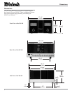
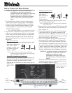
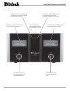
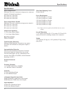
Meter Selection
Rotate the meter mode switch to select the meter operation
mode you desire. Refer to figures 16 and 17.
Lights Off - Meter lights are turned off and the meters will
continue to indicate the power output.
Watts- The meters respond to
all the musical infor-
mation being pro-
duced by the ampli-
fier. They indicate to
an accuracy of at
least 95% of the
power output with
only a single cycle of
a 2000Hz tone burst.
Hold - The meter pointer is locked to the highest
power peak in a sequence of peaks. It is elec-
tronically held to this power level until a
higher power peak passes through the ampli-
fier. The meter pointer will then rise to the
newer higher indication. If no further power
peaks are reached, the meter pointer will very
slowly return to its rest position or lower
power level.
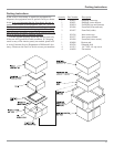
Note: The MC402 Power Output Meters
indicate the wattage delivered to the
Loudspeakers. When in Mono Parallel,
the actual power output is the sum of both
the Right and Left Meter Indications.
Figure 15
Figure 16
Figure 17
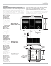
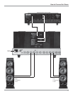
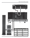
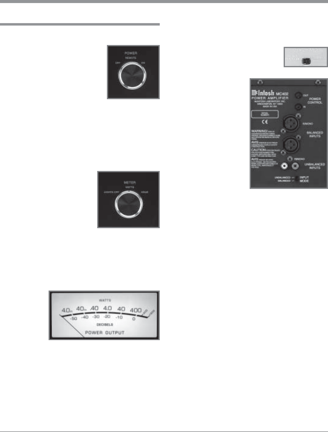
Mode Switches
The MONO PARALLEL/STEREO Mode Switch, which is
located above the Right Channel Outputs
on the Rear Panel of the MC402, allows
selection of either MONO PARALLEL or
STEREO Modes of Operation. Refer to
figures 18.
Note: There is additional
information for
connecting the MC402
and pertaining to both
modes of operation:
“How to Connect
for Stereo” on
pages 10 and 11.
“How to Connect
for Mono
Parallel” on
pages 12 and 13.
The Input Mode Switch,
which is located below the
UNBALANCED INPUTS
on the Rear Panel of the
MC402, allows selection of either the UNBALANCED or
BALANCED Input Connectors. Refer to figure 19.
Figure 19
Figure 18