


9
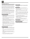
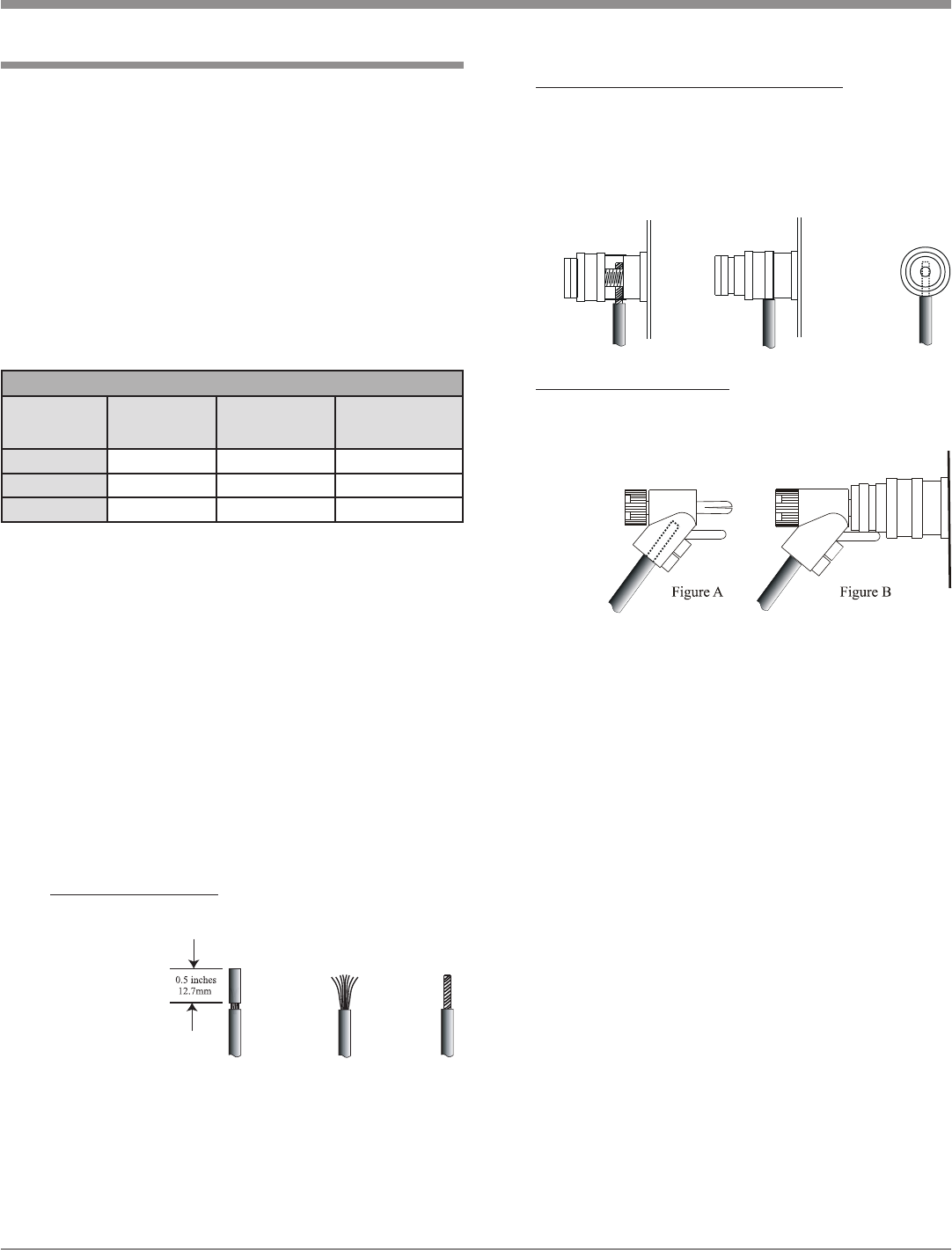
Spade lug or prepared wire connection:
Insert the spade lug connector or prepared section
of the cable end into the terminal side access hole,
and tighten the terminal cap until the cable is firmly
clamped into the terminal so the wires cannot slip
out. Refer to figures 4, 5 & 6.
Banana plug connection:
Insert the banana plug into the hole at the top of the
terminal. Refer to figures A and B.
Note: Banana Plugs are for use in the United States
and Canada only.
3. Connect the Loudspeaker hookup cables from a single
Loudspeaker to the output terminals that match the im-
pedance of the Loudspeaker
1
, being careful to observe
the correct polarities. Output impedance connections
of 2 ohms, 4 ohms and 8 ohms are provided. If the
Loudspeaker’s impedance is in-between the available
connections, use the nearest lower impedance connec-
tion.
WARNING: Loudspeaker terminals are hazardous live
and present a risk of electric shock.
4. Connect the MA6600 Power Cord to a live AC outlet.
Caution: The supplied AC Power Cord should not be
connected to the Rear Panel of the MA6600
Amplifier until after the Loudspeaker Connec-
tions have been made. Failure to observe this
could result in Electric Shock. For additional
instruction on making Loudspeaker Connec-
tions contact your McIntosh Dealer or McIn-
tosh Technical Support.
When connecting Loudspeakers to the MA6600 it is very
important to use cables of adequate size, so there is little to
no power loss in the cables. The size is specified in Gauge
Numbers or AWG (American Wire Gauge). The smaller
the Gauge number, the larger the wire size:
Refer to the Connection Diagram located on the sepa
-
rate folded sheet “Mc1B” when making Loudspeaker
Connections to the MA6600. This an example of a typical
audio system, your system may vary from this, however
the actual Loudspeakers would be connected in a similar
manner.
1. This McIntosh MA6600 Integrated Amplifier is de-
signed for the connection of a single Loudspeaker per
amplifier channel, with an impedance of 2 ohms, 4
ohms or 8 ohms.
Note: The remaining Loudspeaker Terminals on the
Amplifier should not be connected to another
Loudspeaker.
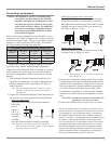
2. Prepare the Loudspeaker Hookup Cables that attach to
the Amplifier by choosing one of the methods below:
Bare wire cable ends:
Carefully remove sufficient insulation from the
cable ends,
refer to
figures 1,
2 & 3. If
the cable is
stranded,
carefully
twist the strands together as tightly as possible.
Note: If desired, the twisted ends can be tinned with
solder to keep the strands together, or attach spade
lug and/or banana connector.
How to Connect
Connecting Loudspeakers
Figure 1
Figure 2
Figure 3
Figure 4
Figure 5
Figure 6
Loudspeaker Cable Distance vs Wire Gauge Guide
Loudspeaker
Impedance
25 feet
(7.62 meters)
or less
50 feet
(15.24 meters)
or less
100 feet
(30.48 meters)
or less
2 Ohms
12AWG 10AWG 8AWG
4 Ohms
14AWG 12AWG 10AWG
8 Ohms
16AWG 14AWG 12AWG
1
For the best performance it is important to minimize an im-
pedance mismatch. An impedance mismatch can occur when
a Loudspeaker of a given impedance rating is connected to
the MA6600 Output Terminals with a different impedance
rating. For example, a Loudspeaker with an impedance rating
of 2 Ohm is connected the MA6600 8 Ohm Output Termi-
nals. The impedance of a Loudspeaker actually varies as the
Loudspeaker reproduces different frequencies. As a result,
the nominal impedance rating of the Loudspeaker (usually
measured at a midrange frequency) might not always agree
with the impedance of the Loudspeaker at low frequencies
where the greatest amount of power is required.