


8
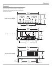
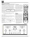
Connecting Components
The MA6600 has the ability to automatically switch power
On/Off to McIntosh Source Components via the Power
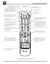
Control connections. The Data Port Connections allow for
the remote operation of basic functions using the MA6600
Remote Control. With an external sensor connected to the
MA6600, remote control operation of the system is possi-
ble from another room and/or when the MA6600 is located
in a cabinet with the doors closed.
The connection instructions below, together with the
MA6600 Input and Output Connection Diagrams located
on the separate folded sheet “Mc1A/1B”, are an example of
a typical audio system. Your system may vary from this,
however the actual components would be connected in a
similar manner. For additional information refer to “Con-
nector and Cable Information” on page 4.
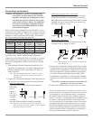
Power Control Connections:
1. Connect a Control Cable from the MA6600 POWER
CONTROL MAIN Jack to the Power Control In on the
McIntosh Turntable.
2. Connect a Control Cable from the McIntosh Turntable
Power Control Out Jack to the McIntosh Audio/Video
Player Power Control In Jack.
3. Connect a Control Cable from the McIntosh Audio/
Video Player Power Control Out Jack to the McIntosh
SACD/CD Player Power Control In Jack.
4. Connect a Control Cable from the McIntosh SACD/CD
Player Power Control Out Jack to the McIntosh Music
Server Power Control In Jack.
5. Optionally connect a Control Cable from the MA6600
POWER CONTROL OUTPUT 2 Jack to the McIntosh
Power Amplifier (Secondary Room) Power Control In
Jack.
6. Connect any additional McIntosh Components in a
similar manner, as outlined in steps 1 thru 4.
Data Control Connections:
7. Connect a Control Cable from the MA6600 CD DATA
PORT Jack to the McIntosh SACD/CD Player Data In
Jack.
8. Connect a Control Cable from the MA6600 SERVER
DATA PORT Jack to the McIntosh Music Server Data
In Jack.
9. Connect a Control Cable from the MA6600 DVD
DATA PORT Jack to the McIntosh Audio/Video Player
Data In Jack.
10. Connect any additional McIntosh Components in a
similar manner, as outlined in steps 7 thru 10.
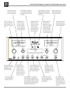
Sensor Connections:
11. Connect a RG59U or RG6U Cable from the MA6600
EXT SENSOR “F” Connector to the McIntosh Sensor
“F” Connector.
Audio Connections:
12. Connect Balanced Cables from the MA6600 CD 1
INPUT Jacks to the McIntosh SACD/CD Player Fixed
Balanced Output Jacks.
13. Connect an Audio Cable from the MA6600 SERVER
INPUT Jacks to the McIntosh Music Server Output
Jacks.
14. Connect an Audio Cable from the MA6600 REC OUT-
PUT Jacks to the McIntosh Music Server Input 3 Jacks.
15. Connect Audio Cables from the MA6600 DVD INPUT
Jacks to the McIntosh Audio/Video Player Output
Jacks.
16. Connect the Audio Cables coming from the Turntable
to the MA6600 PHONO INPUT Jacks.
17. Optionally, connect Audio Cables from the MA6600
OUTPUT 2 Jacks to the McIntosh Power Amplifier
(Secondary) Input Jacks.
18. Connect any additional McIntosh Components in a
similar manner, as outlined in steps 12 thru 17.
Ground Connections:
19. Connect the Ground Cable coming from the Turntable
to the MA6600 GND Binding Post.
AC Power Cords Connections:
20. Connect the MA6600 and any remaining components’
AC Power Cords to a live AC outlet as illustrated.