


9
How to Connect the C2300
How to Connect the C2300
The C2300 has the ability to automatically switch power
On/Off to McIntosh Source Components via the Power
Control connections. The Data Port Connections allow for
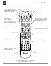
the remote operation of basic functions using the C2300
Remote Control. With an external sensor connected to the
C2300, remote control operation of the system is possible
from another room and/or when the C2300 is located in a
cabinet with the doors closed.
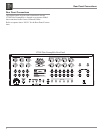
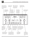
The connection instructions below, together with the
C2300 Input and Output Connection Diagrams located on
the separate folded sheets “Mc1A/1B and Mc2A/2B”, is
an example of a typical audio system. Your system may
vary from this, however the actual components would be
connected in a similar manner. For additional information
refer to “Connector and Cable Information” on page 4.
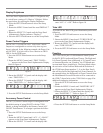
Power Control Connections:
1. Connect a Control Cable from the C2300 POWER
CONTROL ACC(C) Jack to the Power Control In on
the McIntosh SACD/CD Player.
2. Connect a Control Cable from the McIntosh SACD/CD
Player Power Control Out jack to the McIntosh D/A
Converter Power Control In Jack.
3. Connect a Control Cable from the McIntosh D/A Con-
verter Power Control Out jack to the McIntosh Tuner
Power Control In Jack.
4. Connect a Control Cable from the McIntosh Tuner
Power Control Out jack to the McIntosh Music Server
Power Control In Jack.
5. Connect a Control Cable from the C2300 POWER
CONTROL MAIN Out jack to the McIntosh Power
Amplifier Left Channel Power Control In Jack. Con-
nect a Control Cable from the Left Channel Power Am-
plifier Power Control Out to the Right Channel Power
Amplifier Power Control In Jack.
6. Optionally connect a Control Cable from the C2300
POWER CONTROL OUTPUT 1 jack to the McIntosh
Power Amplifier (Secondary Room) Power Control In
Jack.
7. Connect any additional McIntosh Components in a
similar manner, as outlined in steps 1 thru 4.
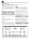
Data Control Connections:
8. Connect a Control Cable from the C2300 TUNER
DATA PORTS Jack to the McIntosh TUNER1 Data In
Jack.
9. Connect a Control Cable from the C2300 CD DATA
PORT Jack to the McIntosh SACD/CD Player Data In
jack.
10. Connect a Control Cable from the C2300 SRVR DATA
PORT Jack to the McIntosh Music Server Data In jack.
11. Connect a Control Cable from the C2300 D/A DATA
PORT Jack to the McIntosh D/A Converter Data In
jack.
12. Connect any additional McIntosh Components in a
similar manner, as outlined in steps 8 thru 11.
Sensor Connections:
13. Connect a RG59U or RG6U Cable from the C2300
EXT SENSOR “F” Connector to the McIntosh Sensor
“F” Connector.
Audio Connections:
14. Connect an Audio Cable from the C2300 TUNER
INPUT Jacks to the McIntosh TUNER1 Fixed Output
Jacks.
15. Connect Balanced Cables from the C2300 CD INPUT
Jacks to the McIntosh SACD/CD Player Fixed Bal-
anced Output Jacks.
Note: Unbalanced Audio Cables may be used instead of
the Balanced Cables, but not both.
16. Connect an Audio Cable from the C2300 SRVR IN-
PUT Jacks to the McIntosh Music Server Output Jacks.
17. Connect an Audio Cable from the C2300 SRVR OUT-
PUT Jacks to the McIntosh Music Server Input 1 Jacks.
18. Connect an Balanced Cables from the C2300 D/A
OUTPUT Jacks to the McIntosh D/A Converter output
Jacks.
19. Connect the Audio Cables coming from the Turntable
to the C2300 MC PHONO INPUT Jacks.
Note: If the Turntable has a Moving Magnet Cartridge
connect the audio cables to the C2300 MM PHONO
INPUT instead of the MC Input.
20. Connect Balanced Cables from the C2300 MAIN
OUTPUT jacks to the McIntosh Power Amplifiers
(Main Left and Right) Input jacks.
21. Connect an Audio Cable from the C2300 OUTPUT 1
jacks to the McIntosh Power Amplifier (Secondary)
Input jacks.
22. Connect any additional McIntosh Components in a
similar manner, as outlined in steps 14 thru 21.
Optional “PassThru” Connections:
23. Connect Audio Cables or Balanced Cables from the
McIntosh MX Series A/V Control Center Front Left
and Right Channel Outputs to the CDR Input Jacks.
24. Connect a Control Cable from the C2300 PASSTHRU
to McIntosh MX Series A/V Control Center Zone A
Power Control Output.
Ground Connections:
25. Connect the Gound Cable coming from the Turntable
to the C2300 GND Binding Post.
AC Power Cords Connections:
26. Connect the C2300 and any remaining components’
AC Power Cords to a live AC outlet as illustrated.