


4
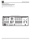
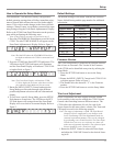
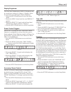
XLR Connectors
Below is the Pin configuration for the XLR Balanced Input
and Output Connectors on the C2300. Refer to the dia-
grams for connections:
PIN 1: Shield/Ground
PIN 2: + Output
PIN 3: - Output
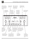
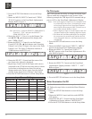
Power Control and Trigger Connectors
The C2300 Power Control and
Trigger Output Jacks send Power
On/Off Signals when connected to
McIntosh and other Components. An
additional connection on the Main
Power Control Jack is for controlling
the illumination of the Power Output
Meters on McIntosh Power Ampli
-
fiers. A 1/8 inch stereo mini phone
plug is used for connection to the
Power Control and Trigger Outputs
on the C2300.
Note: The Data, Power Control and
Trigger Connecting Cable is
available from the McIntosh
Parts Department:
Data, Power Control and Trig-
ger Cable Part No. 170-202
Six foot, shielded 2 conductor,
with 1/8 inch stereo mini phone plugs on each end.
Data Port Connectors
The C2300 Data Out Ports send Remote Control Signals to
McIntosh Source Components. A 1/8
inch stereo mini phone plug is used for
connection.
General, Connector and Cable Information
Connector and Cable Information
Data
Signal
N/C
Data
Ground
PIN 2 PIN 1
PIN 3
PIN 1
PIN 2
PIN 3
Trigger
Control
Ground
N/C
1. The C2300 uses Vacuum Tubes for amplifying the
audio signal. The C2300 is designed to have only quali-
fied Service Personnel perform any part(s) replacement
including all the vacuum tubes.
2. For additional connection information, refer to the
owner’s manual(s) for any component(s) connected to
the C2300 Tube Preamplifier.
3. The Main AC Power going to the C2300 and any other
McIntosh Component(s) should not be applied until all
the system components are connected together. Failure
to do so could result in malfunctioning of some or all of
the system’s normal operations. When the C2300 and
other McIntosh Components are in their Standby Power
Off Mode, the Microprocessor’s Circuitry inside each
component is active and communication is occurring
between them.
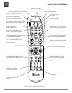
4. Up to two Sensors can be wired in parallel for Remote
Control of the C2300 from other rooms.
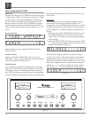
5. Balanced and Unbalanced Inputs and Outputs can be
mixed. For example, you may connect signal sources to
Unbalanced Inputs and send signals from the Balanced
Outputs. You can also use Balanced and Unbalanced
Outputs simultaneously, connected to different Power
Amplifiers.
General Information
Power
Control
Meter
Illumination
Control
Ground
Main Output Jack
Power
Control
Ground
N/C
Output 1 and 2, ACC
Jacks