


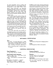
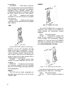
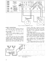
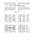

Figure 16. Turntables feeding low-level inputs.
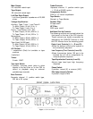
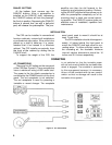
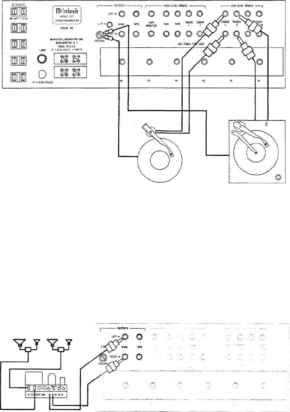
OUTPUT CONNECTIONS
There
are two
sets
of
outputs
on the
left
half of the back panel. (See Figure 15) One
pair is marked MAIN. The second pair is
marked TAPE.
The MAIN outputs connect to power
amplifiers (figure 17). The TAPE output feeds
a tape recorder.
The
MAIN
jacks
are fed
from
cathode
followers. Longer cables than are normally
supplied can be connected between the C22
and the amplifiers. The length of the cable is
limited by the capacity of the cable. The total
capacity must not exceed 1000 mmf. For
instance: cables with a capacity of 25 mmf
per foot may be 40 feet long; 13.5 mmf per
foot cable may be 75 feet long. The input
impedance of the amplifiers should be
50,000 ohms or greater.
The TAPE output is fed from a cathode
follower. The program material fed out of the
TAPE output is not affected by these front
panel controls: VOLUME control, BASS con-
trols, LF and HF filter switches, BALANCE
control, LOUD switch, TAPE switch, PHASE
switch, TREBLE controls, and MODE SELEC-
TOR switch.
The program material fed out of the TAPE
output is affected by these front panel con-
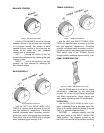
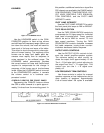
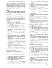
Figure 17. MAIN OUTPUT Connected to
Power Amplifiers.
10