


Connections and Control Settings 7
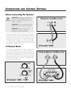
Line Level Input Signal Connection (figure 3):
Connect the left and right line level outputs of your pream-
plifier to the left and right 'Line Level Input' connections of
the Dynamo 300 using quality RCA interconnects. If your
preamplifier only has one set of outputs you may need to
obtain Y adapters from your dealer.
Speaker Level Input Signal Connection (figure 4):
Connect the left and right outputs of your amplifier to the
subwoofer’s left and right 'Speaker Level Input' binding
posts. Use quality speaker cable.
If your amplifier only has one set of outputs you may
connect your amplifier to your speakers as normal and
run an additional set of cables from your speakers to the
subwoofer’s 'Speaker Level Input' binding posts.
It is also possible to connect the left and right outputs of
your amp to the left and right 'Speaker Level Input' of the
subwoofer and run additional cables from your subwoofer
to the speakers.
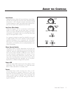
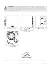
Recommended Control Settings (see figure 2):
1
Set the 'Low Pass Filter' knob to approximately
70% of
your loudspeakers lowest frequency response.
3 While playing music with bass content, turn the 'Level'
control up until the music has deep extended bass,
being careful to avoid levels that become overwhelming.
4 Try the 'Phase' control in different settings until the best
blending is obtained.
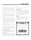
Multi-Channel/LFE Mode
This setup is recommended if your Dynamo 300 will be used
in a dedicated home theater or multi-channel system. When
a signal is connected to the subwoofer’s LFE input, and the
crossover switch is set to 'Bypass (LFE In)' the internal low
pass filter is not active. By following this setup, you will allow
your processor to handle most of the bass management.
If you will be using your system for both 2-channel and
multi-channel listening we recommend using this setup
and connection method. Some modern receivers and
processors allow users to route left and right channel
low-frequency information, in addition to discrete LFE infor-
mation, through the LFE output.
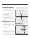
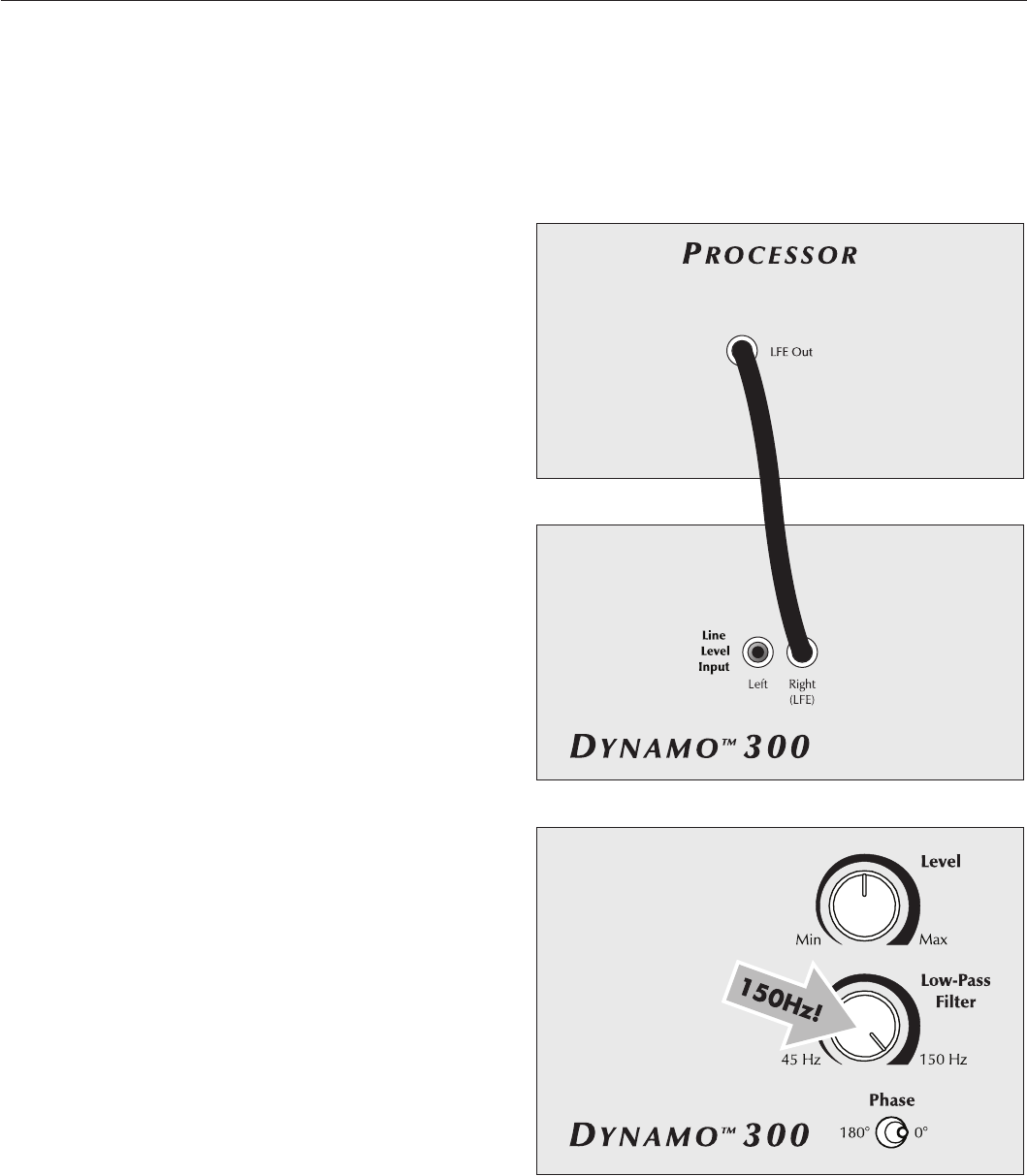
Figure 5. Signal connection for multi-channel mode.
Figure 6. For Multi-channel/LFE mode set the Low-Pass Filter at 150Hz.
Adjust Level and Phase controls.