


24
Mark Levinson
Link2
The main purpose of the Mark Levinson Link2 protocol is to allow a
single “master” device to control other “slave” devices. Refer to the
product documentation of each Mark Levinson product to verify
compatibility and cabling requirements.
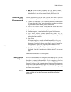
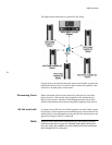
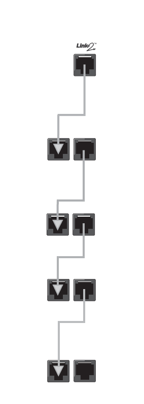
To use Link2, all devices are daisy-chained together as demonstrated
in the figure on the left. Each “chain” can have only one master
device; all other devices in the chain become slaves. Slave devices
receive and respond to the commands of the master device. The
Nº53 amplifer is always a slave device.
Ensure that all components are powered off before connecting the Link2
ports and ensure that there are no audio sources active. Once connected,
power on the linked components one at a time to ensure proper
functioning of the Link2 controls. The master device must be
powered on first.
Allow each component to complete the initialization sequence
before proceeding to the next component. When all components
have been powered on, put the master device into Standby mode
again. Link2 does not activate until the master device is put into
Standby mode (after initial power-up).
The Nº53 slave(s) can perform the following Link2 functions:
• Synchronized LEDs – the Standby LED of the Nº53 blinks in
unison with the master device.
• Standby Link – the master device controls the Standby state
of the Nº53 amplifier.
• Fault Condition Reporting – if the Nº53 experiences a fault
condition, the fault is reported on the master device.
The Nº53 uses 8-to-8 pin Cat 5 or link cable. Older products use
8-to-6 pin link cable. We recommend using Cat 5 cables for greater
quality and noise immunity.
MASTER
COMMUNICATION
PORT
SLAVEªIN
SLAVEªIN
AMPLIFIER
SLAVEªIN
AMPLIFIER
SLAVEªIN
AMPLIFIER
AMPLIFIER
SLAVEªOUT
SLAVEªOUT
SLAVEªOUT
SLAVEªOUT