


ENGLISH
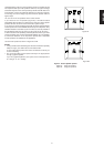
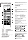
LOCATION AND FUNCTION OF PARTS AND CONTROLS
Rear panel connections
(See pages 108 )
All connections to the rear panel should be made with entire power off to
the system. To avoid miss-connection, it is advisable to connect one cable
at a time between the different components. This is the safest way to
avoid cross-connecting channels or mix-up signal inputs with outputs.
A FM antenna terminal (75 ohm or 300 ohm)
For connecting an external FM antenna with a coaxial cable, or for
connecting a cable network.
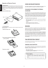
AM antenna and ground terminals
For connecting the supplied AM loop antenna. Use the terminals
marked “AM” and “GND”.
The supplied AM loop antenna will provide good AM reception in most
areas. Position the loop antenna to the best reception.
B VCR1 video input/output jacks
Connect the IN jack to your main VCR’s video output jack and connect
the OUT jack to the VCR’s video input jack.
C LD/TV video input jack
Connect to a laser disc player’s video output or TV's output jack.
D DVD video input jack
Connect to a DVD's video output.
E TV MONITOR OUT jack
Connect to a TV’s video input jack.
F REMOTE jacks
Connect to other Marantz components equipped with REMOTE jacks.
(See page 8.)
Marantz components utilize the Philips RC-5 remote control
system language.
G TAPE 1 input jacks
Connect the output (PLAY) jack of the cassette deck to the IN jack.
H TAPE 2 input jacks
Connect the output (PLAY) jack of the cassette deck to the IN jack.
I CD input jacks
Connect to the audio output jacks of a CD player.
J VCR1 audio input/output jacks
Connect the IN jacks to a VCR’s audio output jacks and the OUT jacks
to the VCR’s audio input jacks.
K DVD audio input jacks
Connect the IN jacks to a VCR's/DVD's audio output jacks.
L LD/TV audio input jacks
Connect to the audio output jacks of a laser disc player or TV.
M PRE OUT (FRONT, CENTER AND REAR JACKS)
These jacks supply pre-amp output signals, and are used for connection
to external power amplifiers (if necessary).
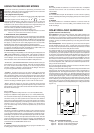
N SURROUND speaker output terminals
Connect to the surround (rear) speakers.
O CENTER speaker output terminals
Connect to the center speaker.
P FRONT speaker output terminals
Connect to the front speakers.
Q AC OUTLET
Connect the AC power cables of a CD player, cassette deck, etc., of
your system. The power supply from switched outlet is interlocked
with the POWER switch of the unit. The maximum total power
consumption of the connected components must not exceed the
following limit:
100 W MAX.
R AC power cord
Plug into AC 230V household outlet.
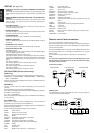
S COAX. input terminal
Connect the COAX. output jack of the (digital equipment) Player to the
IN jack.
OPT. input terminal
Connect the OPT. output jack of the (digital equipment) Player to the IN
jack.
IMPORTANT NOTE:
These input jacks are for DTS, AC-3 / PCM digital signals only.
Do not connect standard audio outputs to these DTS, AC-3 / PCM digital
input jacks.
T 6ch direct in
Connect the output jack of the surround processor (e.g. Marantz DP870
etc.) to the IN jack.
Note on loudspeaker impedance:
The power ratings specified for this Marantz receiver are obtained using
fixed value test load impedances. However, the actual impedance of a
loudspeaker system will vary with frequency, deviating from the nominal
rating. This Marantz amplifier will drive any modern loudspeaker system
with a rated impedance of 8 ohms or higher. A few newer loudspeakers
feature impedances of less than 8 ohms. The high current output capability
of this Marantz receiver can provide the additional power necessary to
drive such low impedance speakers. However, during extended passages
of high volume, the protection circuitry may temporarily interrupt opera-
tion. If this occurs, simply reduce the volume accordingly. The protection
circuitry is specially designed so that it cannot affect the sound quality
during normal operation.
6