


ENGLISH
13
IN
MONITOR
VCR1
RSR
C
SW SBR
SL SBLL
R
SPEAKER SYSTEMS 6
-
8 OHMS
CENTER
R
FRONT SURROUND BACK SURROUND
LLLR
DVD
OUT
IN
MONITOR
TVDVDVCR1
OUTIN
DSS
/
VCR2
OUT
VIDEO
IN
OPT.
OUT
21
7.1CH INPUT
L SL C SBL
SBRSWSRR
TVDVDVCR1
OUTININ OUT
DSS
/
VCR2
IN OUT
CDR/MDTAPE
PRE OUT
OUTIN
CD
R
L
FM
(
75
Ω
)
GND AM
AUDIO
ANTENNA
DIGAUDIO
S-
VIDEO
S. SPEAKER B
LR
AUDIO
OUT
DIGITAL
OUT
VIDEO
OUT
AUDIO
OUT
LR
VIDEO
OUT
S-VIDEO
IN
VIDEO
IN
L R
L R
MONITOR
TV
MONITOR
VCR1
S-
VIDEO
TV
2
DSS
/
VCR2
IN
IN
DSS
/
VCR2
L R
L R
L R
IN OUT
MONITOR
VCR1
MONITOR
R
C
SW SBR
L
SBL
R
SPEAKER SYSTEMS 6
-
8 OHMS
CENTER
R
FRONT SURROUND BACK SURROUND
LLLR
DVD
OUT
IN
MONITOR
TVDVDVCR1
OUTIN
DSS
/
VCR2
OUT
VIDEO
IN
Y
DSS
/
VCR
2
DVD
COAX.
OUT
43OPT.
OUT
21
7.1CH INPUT
L SL C SBL
SBRSWSRR
TVDVDVCR1
OUTININ OUT
DSS
/
VCR2
IN OUT
CDR/MD
P
RE OUT
T
M
C
B
/
P
B
C
R
/
P
R
A
UDIO
RC-5
DIGITAL
COMPONENT VIDEO
AUDIO
AC OUTLET
AC IN
100W MAX.
230V 50H
Z
SWITCHED
S-
VIDEO
S. SPEAKER B
VCR1
OUTIN
VCR1
OUTIN
DVD
DVD
MONITOR
VCR1
DVD
OUT
IN
S-
VIDEO
MONITOR
Y
DVD
C
B
/
P
B
C
R
/
P
R
COMPONENT VIDEO
3
DIGITAL
LR
AUDIO
OUT
DIGITAL
OUT
VIDEO
OUT
S-VIDEO
OUT
S-VIDEO
IN
LR
AUDIO
OUT
AUDIO
IN
LR
VIDEO
OUT IN
S-VIDEO
OUT IN
L R L R
YCB
/
PB CR
/
PR
COMPONENT
VIDEO OUT
YCB
/
PB CR
/
PR
COMPONENT
VIDEO IN
L R L R
L R
L R
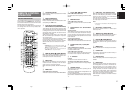
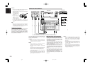
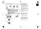
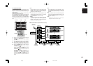
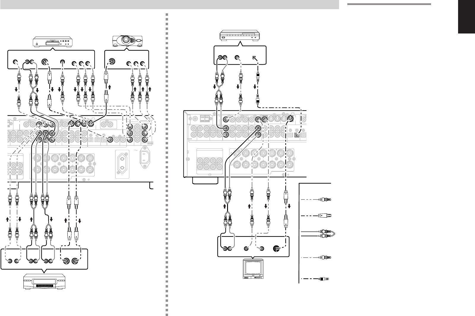
CONNECTING VIDEO COMPONENTS
ANALOG AUDIO
VIDEO
S-VIDEO
DVD PLAYER
VIDEO PROJECTOR
SATELLITE TUNER
DIGITAL AUDIO
(COAXIAL)
VCR
TV
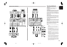
VIDEO, S-VIDEO , COMPONENT JACKS
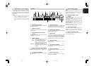
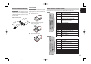
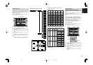
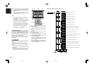
There are 3 types of video jacks on the rear panel.
VIDEO jack
The video signal for the VIDEO jacks is the
conventional composite video signal.
S-VIDEO jack
The video signal is separated into luminance (Y) and
color (C) signals for the S-VIDEO jack. The S-VIDEO
signals enables high-quality color reproduction. If
your video component has an S-VIDEO output, we
recommend to use it. Connect the S-VIDEO output
jack on your video component to the S-VIDEO input
jack on this unit.
Component jack
Make component video connections to a TV or
monitor with component inputs to produce higher
quality video images. Use a component video cable
or 3 video cords to connect the component video
out jacks on the SR4500 to the monitor.
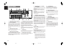
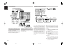
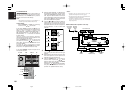
Video convert
The input signals of video and S-video are converted
each other, and each of the converted video signals
can be output.
For example, the video input signal from the VIDEO
jack can be output to the monitor jack of S-VIDEO.
Moreover, the contrary is also possible. Priority is
given to S-VIDEO jack when having input by VIDEO
and S-VIDEO jack from the same source.
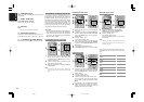
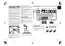
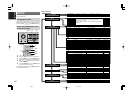
Notes:
•
Be sure to connect the left and right audio channels
properly.
Red connectors are for the R (right) channel, and
white connectors are the for L (left) channel.
• Be sure to connect the inputs and outputs of the
video signals properly.
• If you connect the S-VIDEO or component signal
to the S-VIDEO or component jack on this unit, it
is not necessary to connect the conventional video
signal to the VIDEO (composite) jack. If you use
both video inputs, this unit gives priority to the S-
VIDEO signal.
• Each type of video jack works independently.
Signals input to the VIDEO (composite) and S-
VIDEO jacks or component are output to the
corresponding VIDEO (composite) and S-VIDEO
or component jacks, respectively.
• You may need to setup the digital audio output
format of your DVD player, or other digital source
components. Refer to the instructions of the each
component connected to the digital input jacks.
• There is no Dolby Digital RF input jack. Please
use an external RF demodulator with a Dolby
Digital decoder to connect a video disc player
which has a Dolby Digital RF output jack to the
digital input jack on this unit.
DIGITAL AUDIO
(OPTICAL)
04.5.14, 4:17 PMPage 13