


3
ENGLISH
FRANCAIS
DEUTSCH
NEDERLANDS
ESPANOLITALINO PORTUGUES
SVENSKA
DANSK
DANSK
SVENSKAPORTUGUES ITALINOESPANOL NEDERLANDSDEUTSCH
FRANCAIS
ENGLISH
n ANALOG BALANCED OUTPUT LEVEL
(Analog balanced output level adjustment)
(PMD331/PMD340 only)
Use a Phillips type screwdriver to adjust the analog balanced
output level. Turn the screwdriver clockwise to increase the
output level, and turn the screwdriver counterclockwise to de-
crease the output level. (Min. level = -11 dBu)
Caution
-Do not use excessive force when turning the screwdriver.
-The output level and channel balance are adjusted when the
unit is shipped from the factory. Do not change these adjust-
ments inadvertently.
m ANALOG BALANCED OUTPUT
(Analog balanced output jacks)
(PMD331/PMD340 only)
Connect a device with analog balanced inputs to these jacks
through a cable with XLR connectors.
Note:
When connecting another device to this CD player through
these jacks, confirm that the pin assignments of the XLR con-
nectors match before making the connection.
If the pin assignments are different, change the connections
in the XLR connector cable so that the pin assignments match.
, DIGITAL OUTPUT (SPDIF)
(Digital balanced output jack)
(PMD331/PMD340 only)
Connect a device with a digital balanced input to this jack through
a cable with XLR connectors.
Note:
The digital format output on this balanced connectors is SPDIF.
Most products that contain an XLR digital input are designed
to accept an AES/EBU format signal. Be aware that the AES/
EBU input on some products will not accept SPDIF, even
though the audio data is identical.
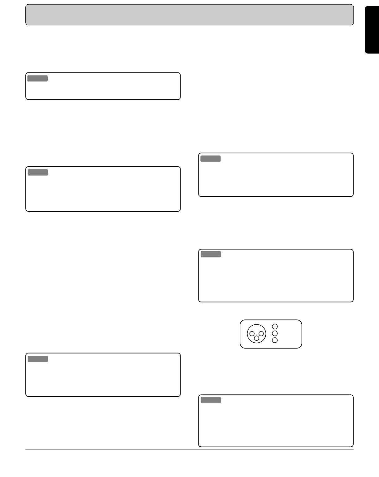
Name and Operation of Each Part *
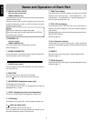
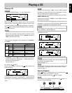
3 COLD(-)
2 HOT(+)
1 GND
1
3
2
z ANALOG OUTPUT
(Analog output jacks)
These are the analog signal output jacks. The red jack is the
right channel audio output, and the white jack is the left chan-
nel audio output jack.
Caution
Do not connect these jacks to the PHONO jacks on an ampli-
fier.
x DIGITAL OUTPUT (SPDIF)
(Digital output jack)
The digital signal from the compact disc that is being played is
output through this jack.
Connect a device with a digital input jack (such as recording
equipment, an amp, or a D/A converter) to this jack through a
RCA cable.
Note:
When outputting a digital signal from the PMD331/PMD340,
set “D.OUT” in the Preset menu to “On”.
For details on how to make this setting.
(See also page 17.)
c FADER START
(Fader start input jack)
An external switch connected to this jack can be used to con-
trol disc pause and playback.
(See also page 19.)
On the PMD331/PMD340, this feature is in the CONTROL I/O
connector ⁄0.
(See also page18.)
v REMOTE INT/EXT
(RC5 remote control internal/external switch)
When using an infrared remote control transmitter to control
this CD player, set this switch to “INT”. When incorporating this
CD player into a system by connecting this CD player (for re-
mote control) to equipment that is equipped with a RC5 com-
patible output, set this switch to “EXT”.
Note:
Please set to “EXT” when you are using this CD player with-
out a remote control. The CD player will then not be able to
receive signals from another infrared remote control transmit-
ter.
b REMOTE RC5 IN/OUT
(RC5 remote control input/output jack)
This CD player can be controlled remotely by connecting this
CD player via a remote control cable to other equipment that
support RC5.
XLR Connector Pin Assignments for this CD Player
- If this CD player is to be connected to equipment that is
equipped with a RC5 remote control jack, be certain to connect
the “REMOTE CONTROL IN” jack on this unit with the
“REMOTE CONTROL OUT” jack on the other unit.
- When this CD player is connected to a cassette recorder or a
disc recorder (CD-R, CD-RW, etc.), RC5 provides synchro re
cording capabilities. (See also page 15.)
* Refer to the figures on the pages at the back of this user’s guide. The callout numbers on the figures correspond to those found in
the text.